Tom,
The house has a footprint of 750 sq ft and is 1.5 stories with cathedral ceiling over the living room and a bedroom up for about 1050 sq ft of finished area. It is a hybrid structure with some parts 2×4 stick built and part of it post and beam roughsawn ash and some oak and cherry round log elements bolted with 3/8″ SPAX bolts.
There are parallel rafters: ash which will be visible inside on the cathedral ceiling, then above those 2×8 #1 SYP 16″ o.c. allowing for a cavity for R70 insulation. Roof pitch is 15/12. Slate 1/4-3/8″ adds 10#’s dead weight to roof load.
Southern Pine http://www.southernpine.com/app/uploads/SPtable26_060113.pdf span table for 30# snow load and 20# dead load says 14′-9″ max span which is much larger than the span of the house which is 18′-8″/2 = 9′-4″. So even if we removed the entire ash frame, except the outermost posts, (assuming the lateral forces were addressed), the roof should stay up.
Below I look at the structure of a traditional hammer beam truss and how in my mind (remember I’m not an engineer), that what I did is essentially a modified hammer beam truss.
Thanks for taking a look at my project.
Greg
Bold print are my comments interspersed with hammer beam info copy and pasted in. Some of this should look obvious–I had put this info in here for the engineer I had been trying to work with.
From website: https://timberframehq.com/tag/hammer-beam/
Hammer Beam Truss

—————————————————————-
A hammer beam truss is what I used when thinking through the structure of the house. In the house I am building, the vertical elements in toward the center come down to the floor, and the 45 degree braces are in a lower position starting at the floor and angling up to the vertical timber. An additional horizontal connection is added where the brace intersects the vertical element. If the traditional hammer beam truss has worked for structures hundreds of years old, I figure what I have built will work as well.

TIMBER FRAMING QUESTIONS & ANSWERS
Stresses in the Hammer Beam Truss
Hi there
I am soon to be taking a course in hammer beam frames, and I am trying to get my head around the stresses in the frame/truss (below the collar tie).
I am wondering if one structural job of the hammer beam (assumed as the elements below the collar tie – hammer beam, vertical post on top and bracing members) ; is to work as a ‘stiff’ beam which simply reduces the lateral deflection/thrust in the top chord/rafter and subsequently reduces the thrust and moment in the top of the wall/buttress/supporting posts.
many thanks for any insight into the fascinating world of timber trusses. Also i wonder if there are any good texts on analysis of timber frames you could recommend.
Many thanks
Ben
Background in Engineering, UK.
Hi Ben, thanks for the question!
Hammer beam (HB) trusses are certainly an engineering marvel, and are one of the most open and regal truss types out there.
Here at VTW we occasionally create traditional HB trusses, but we often work with and design modified HB trusses. Modified HB trusses have more intermediate bracing and webbing and a lower collar tie, but can eliminate the need for buttressing in other parts of the structure. The additional members can help resolve the tension present along the bottom of the truss, unlike a traditional truss. Unless the structure has the ability to resist the outward thrust present at the bottom of the HB truss, the modified HB truss is the way to go. We usually use the hammer beam itself as a robust bending member, as the hammer post (vertical) and brace (into the post) go into significant compression.
Here is an axial load diagram of a traditional HB truss (green->blue is compression, orange->red is tension):
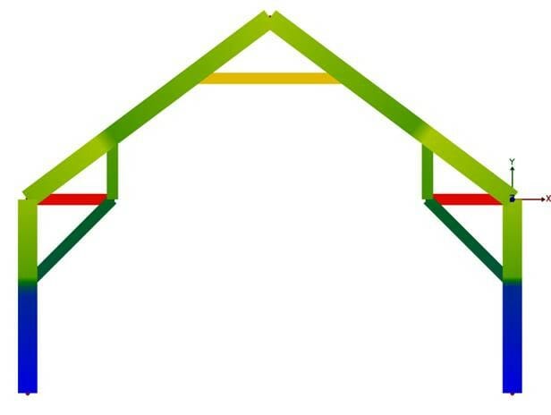
In this instance, the hammer beams are in tension attempting to resolve the compression that is developed in the brace, and is then kicking into the post. Unfortunately with this design, the truss is likely unable to adequately resolve the tension at the eave, and will need a positive connection at each eave with enough stiffness to prevent the lateral deflection.
———————————————————–
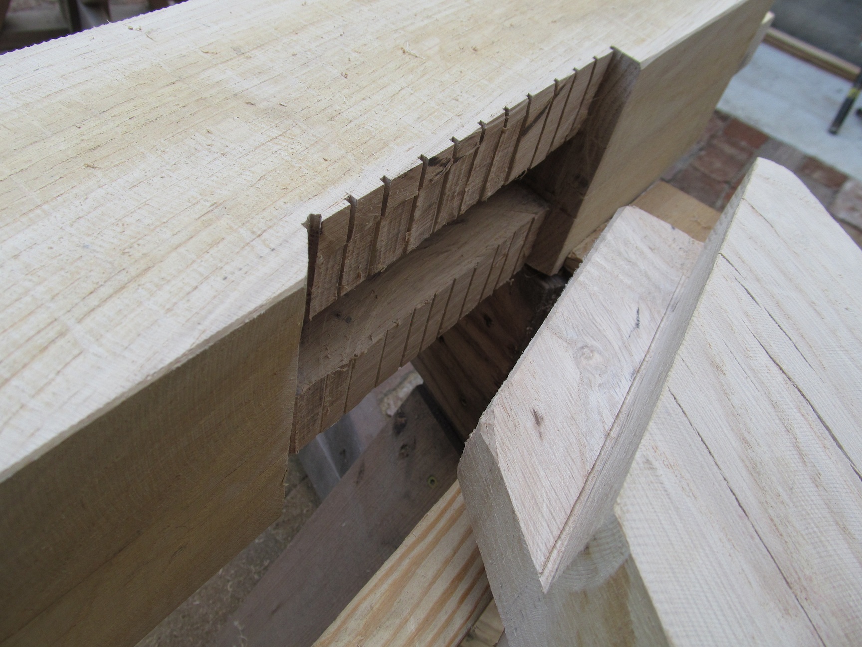
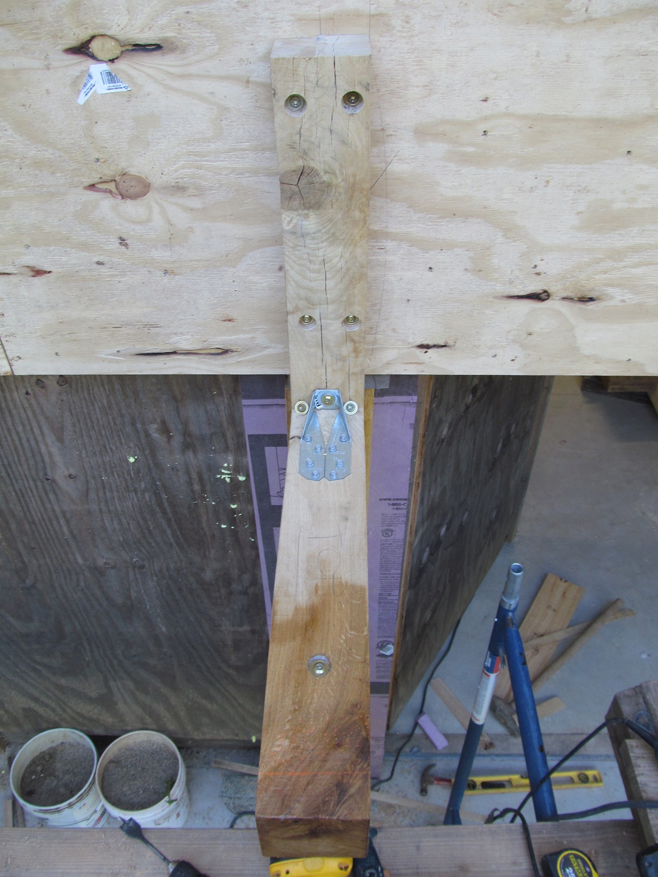
Again, here is my variation with the structure drawn in which I have done, and “x’d” out the parts I do not have. My tie beam is lower than in the picture. I have one 3/8″ SPAX at each end toe screwed at about 30 degrees from vertical into the post (log). This would essentially put the SPAX in shear (rated at 1435#s). It would be quite easy for me to add a steel tie connector to increase the strength.

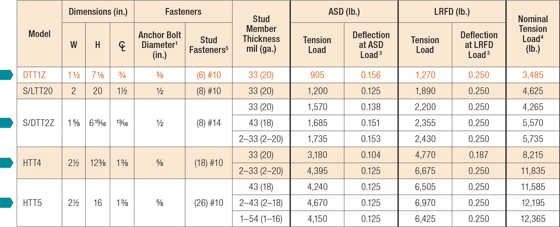
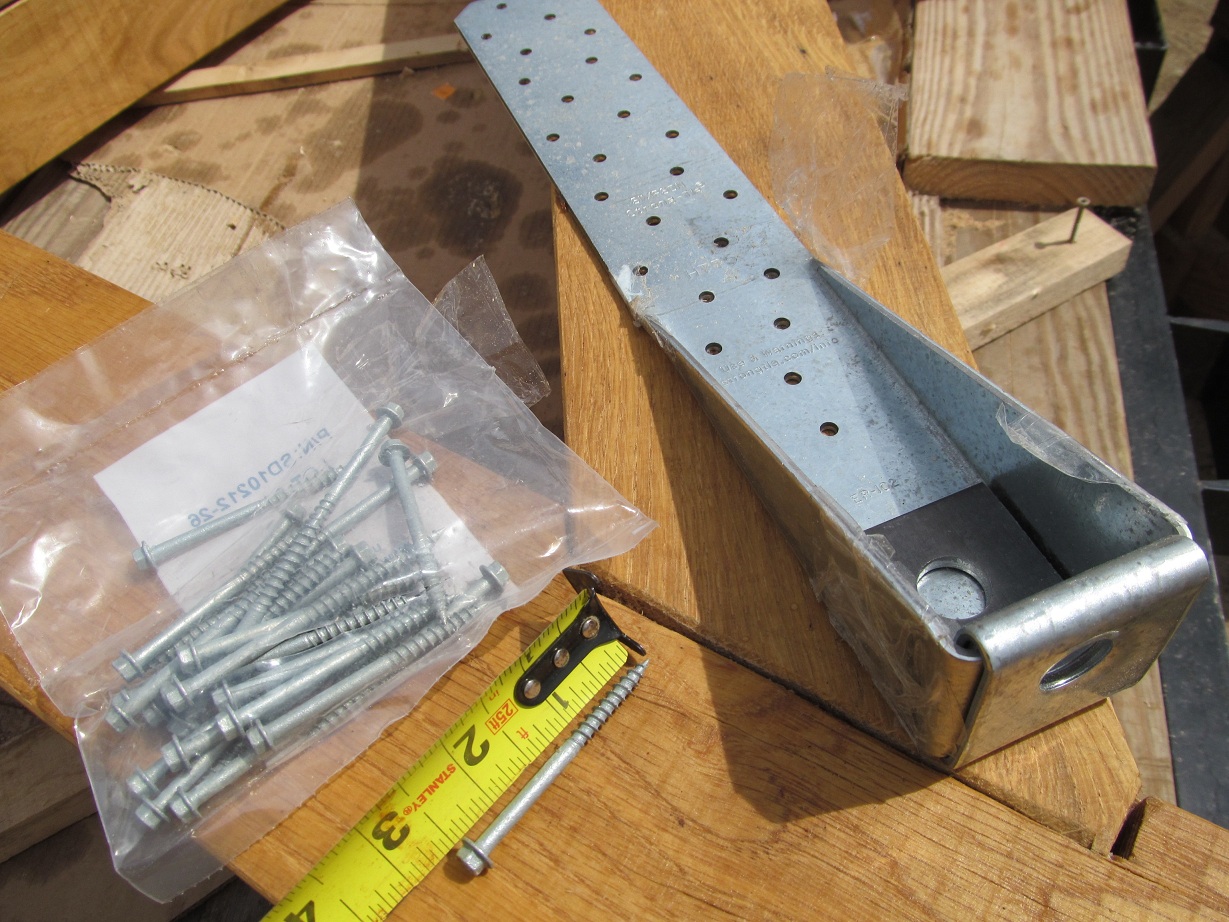
The S/LTT20 from Simpson Strong Tie:  or the HTT4:
 One of these at each end of my horizontal tie (6″round oak) could connect with 1/2″ or 5/8″ all-thread to a similar connector on the outer/upper rafter (2×8″ yellow pine) thus tying the entire assembly together with parts I can buy off the shelf.
——————————————————
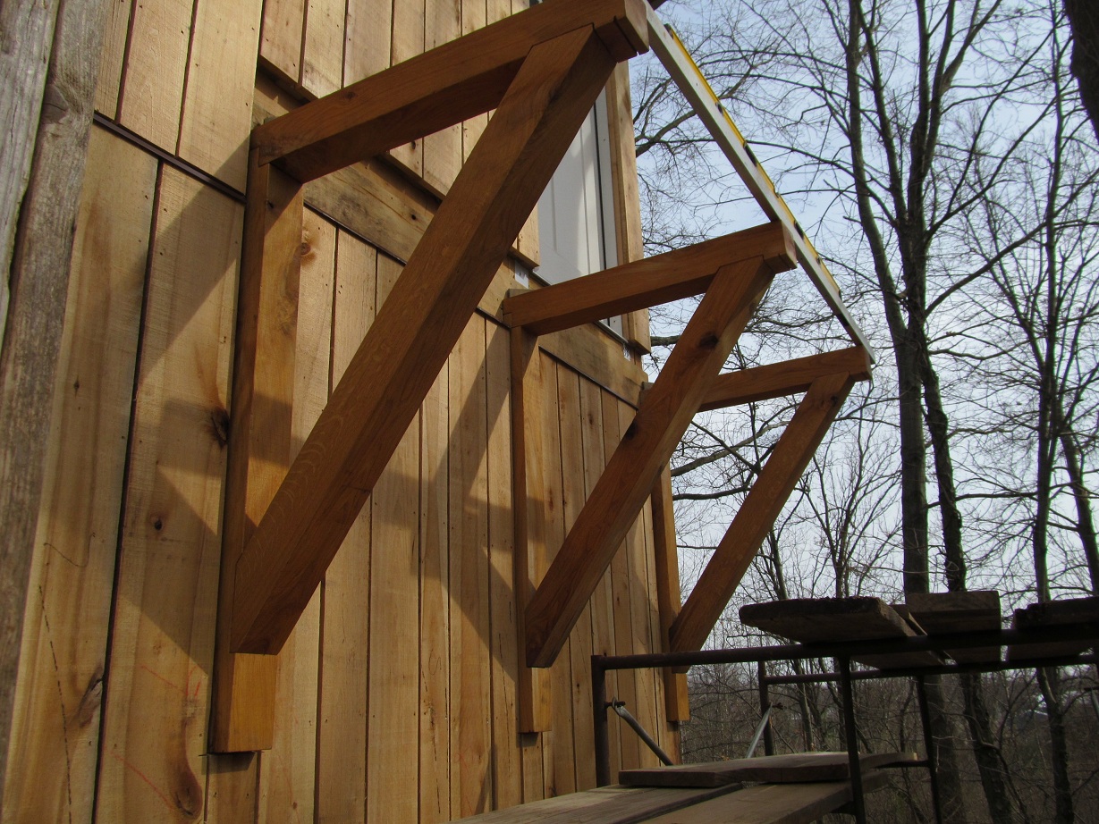
Awning over garage doors is bolted on with 3/8″ SPAX screws. Also and left and right white oak brackets are set on a 5/8″ masonry bolt (it acts like a peg to hang something on) to give support as well.


2nd story balcony pictures:
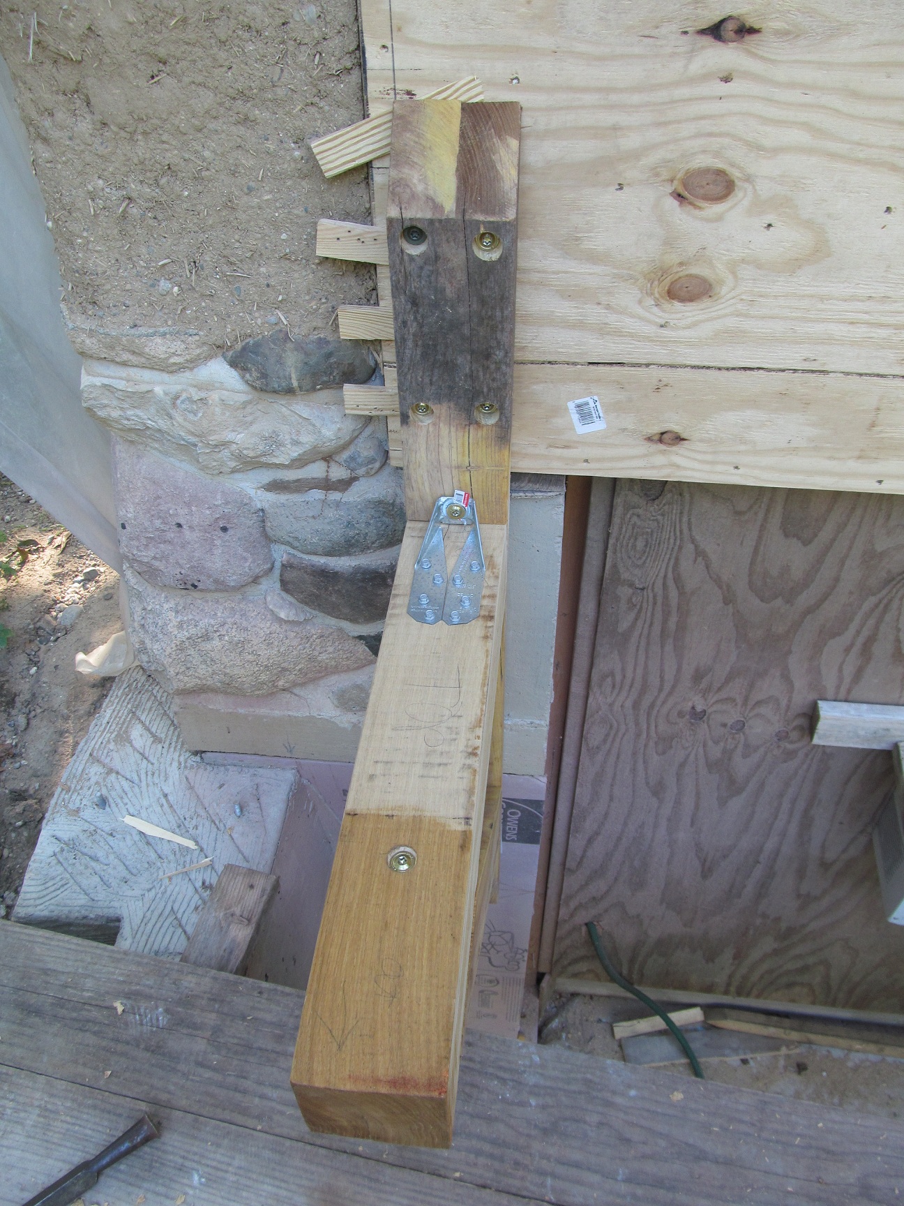
Siding has solid blocking behind where brackets will be:

See under upper door areas for brackets:

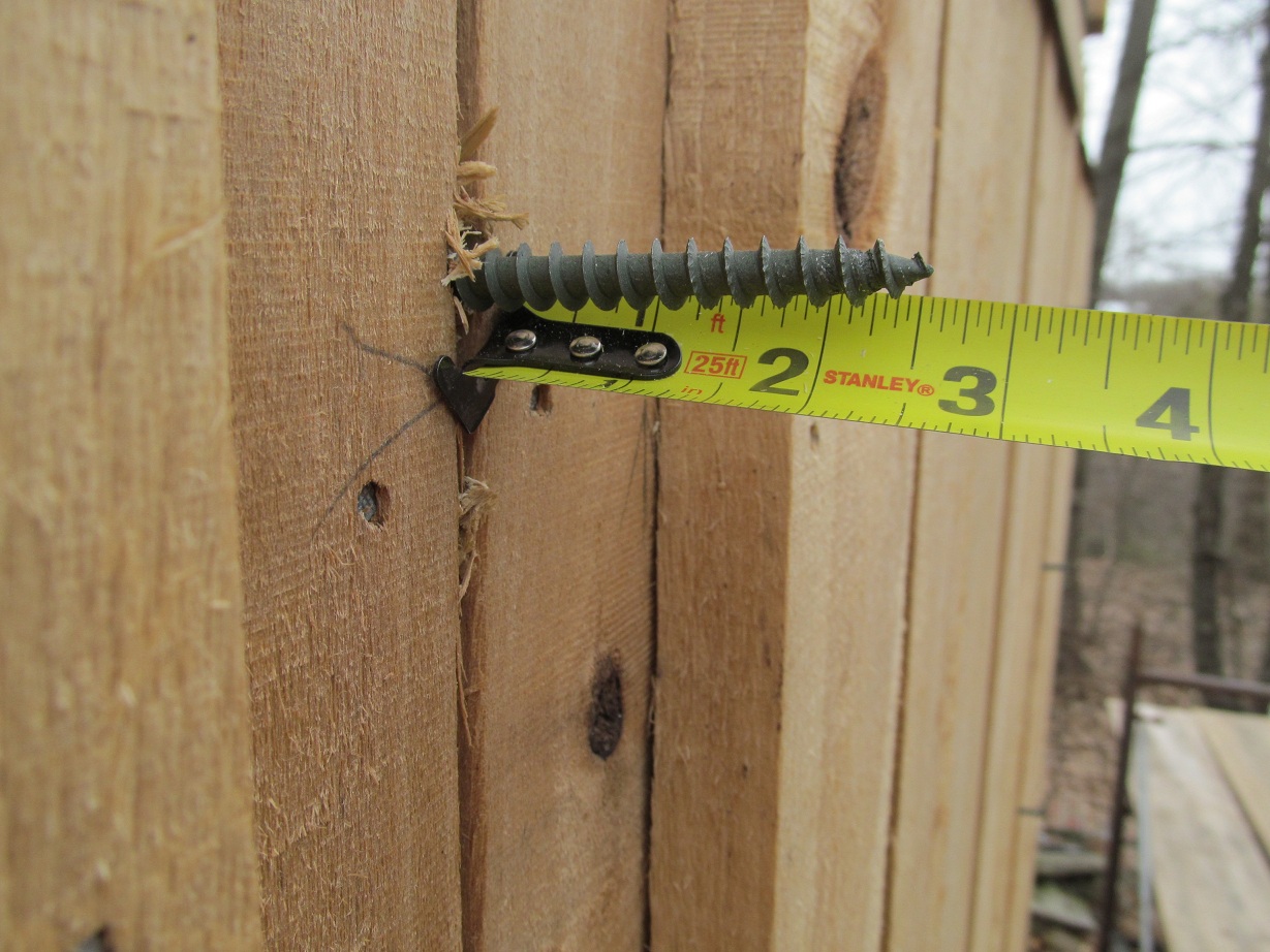
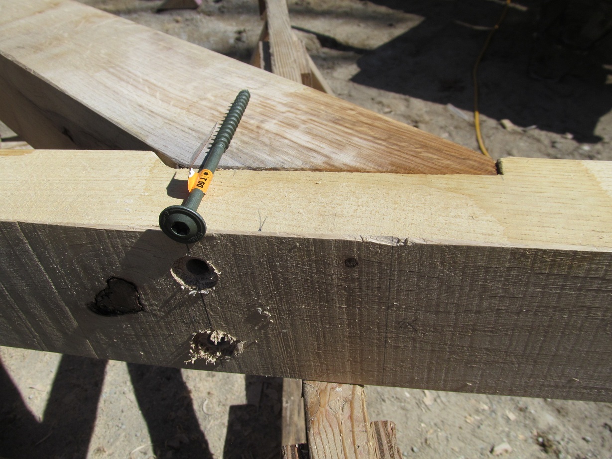
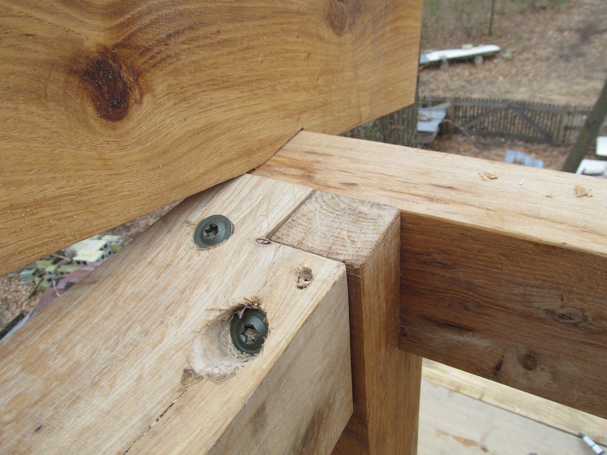
Predrilled from inside wall. Four 3/8″ SPAX will tie into oak 3×5″. (Bolt heads and washers are not pictured as they can will visually inspected from inside the house during a site visit.)

Threads will go into 2 1/2″ of the 3″ thickness of the oak bracket.
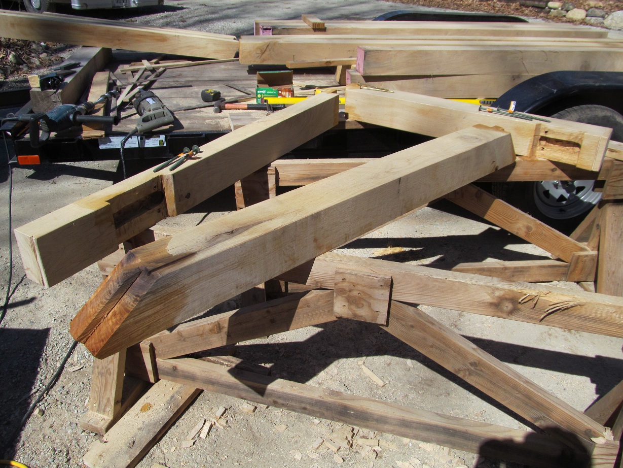
Brackets from 5×5″ and 3×5″ white oak treated with borates, then Thomson’s Water Seal. Brackets have one bolted half lap joint and two housed (1/2″) mortise and tenon joints with 1″ stub tenons 1 1/2″ wide.


Simpson Strong Tie galvanized anchors at floor level:


Brackets bolted in place:
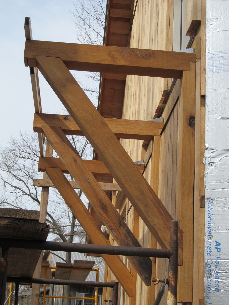
5×5″ posts and 3×5″ top plate:

Simpson Strong Tie galvanized connectors at top of porch structure:


3/8″ SPAX at top of porch structure:
1/4″ SPAX bolts into wall and into top plate:


Purlins gun nailed down with galvanized ring shank nails:
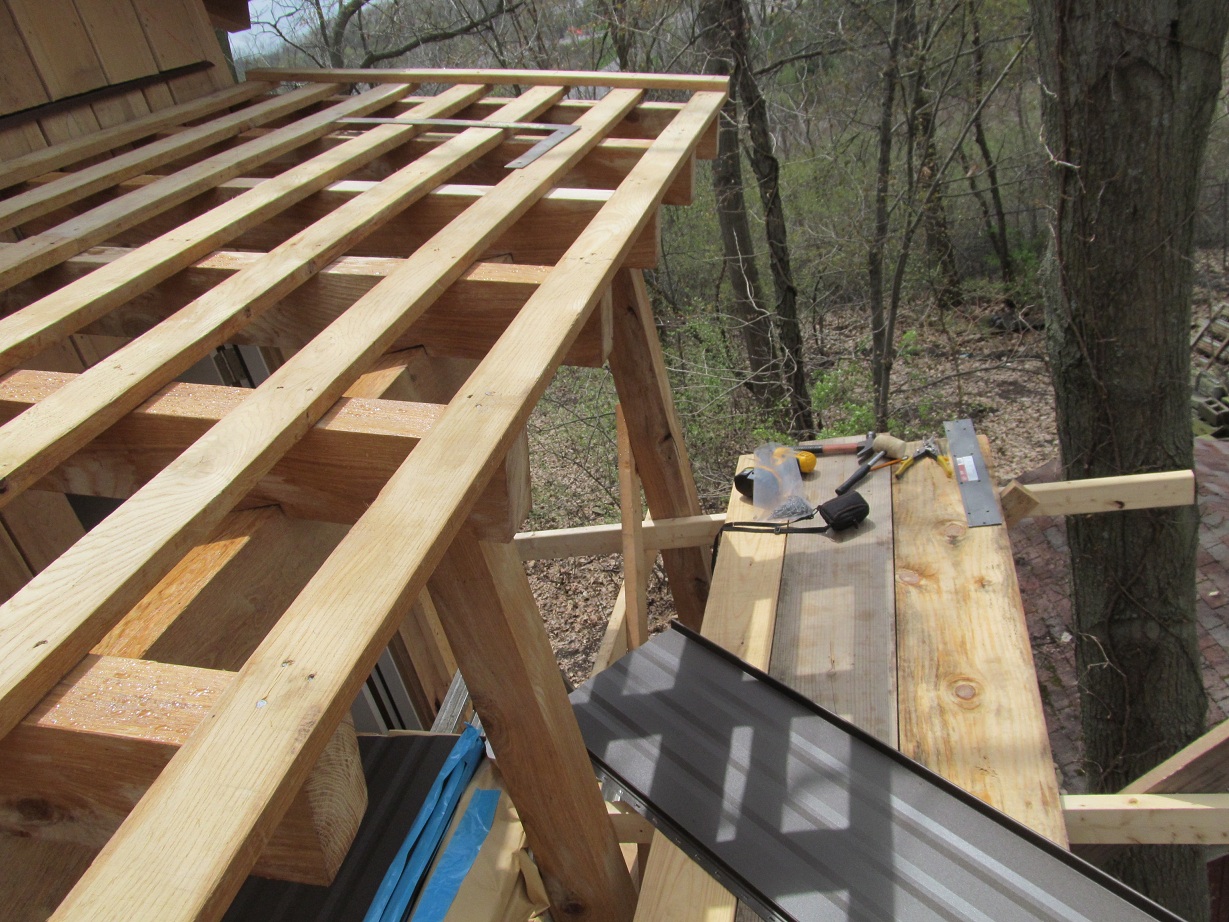
Slate roof is 1/4-3/8″ thick. Table below is from Camara Slate website:
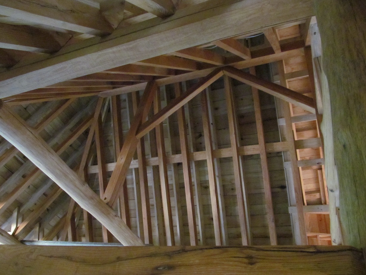
July 10th. King posts are 5×5″ ash. The ridge beam is around 19′ from where it bears on a wall that goes down to a footer and where it ends in the hip. It has a top chord of 2×12 and bottom chord is a 2×6″. The depth is close to 3′. (This is above the 5×8″ ash ridge seen in the pictures below.)


Beginning of cob cavity wall. 11″ thick outer leaf and 8″ thick inner leaf. 7″ cavity of 2 layers of 3.5″ R15 mineral wool. White oak and black locust 1/2″x 1 or 1.25″ ties connected with deck screws.


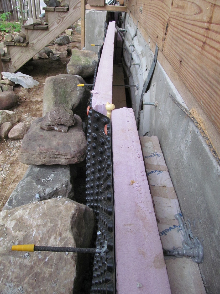
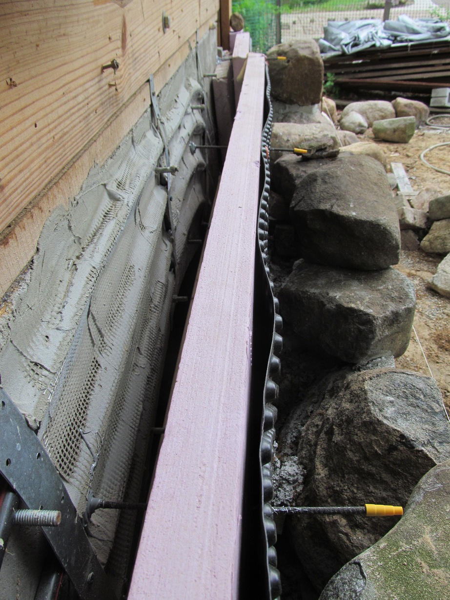


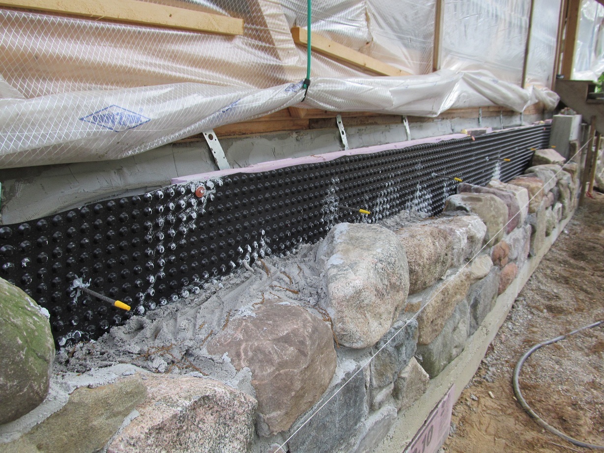
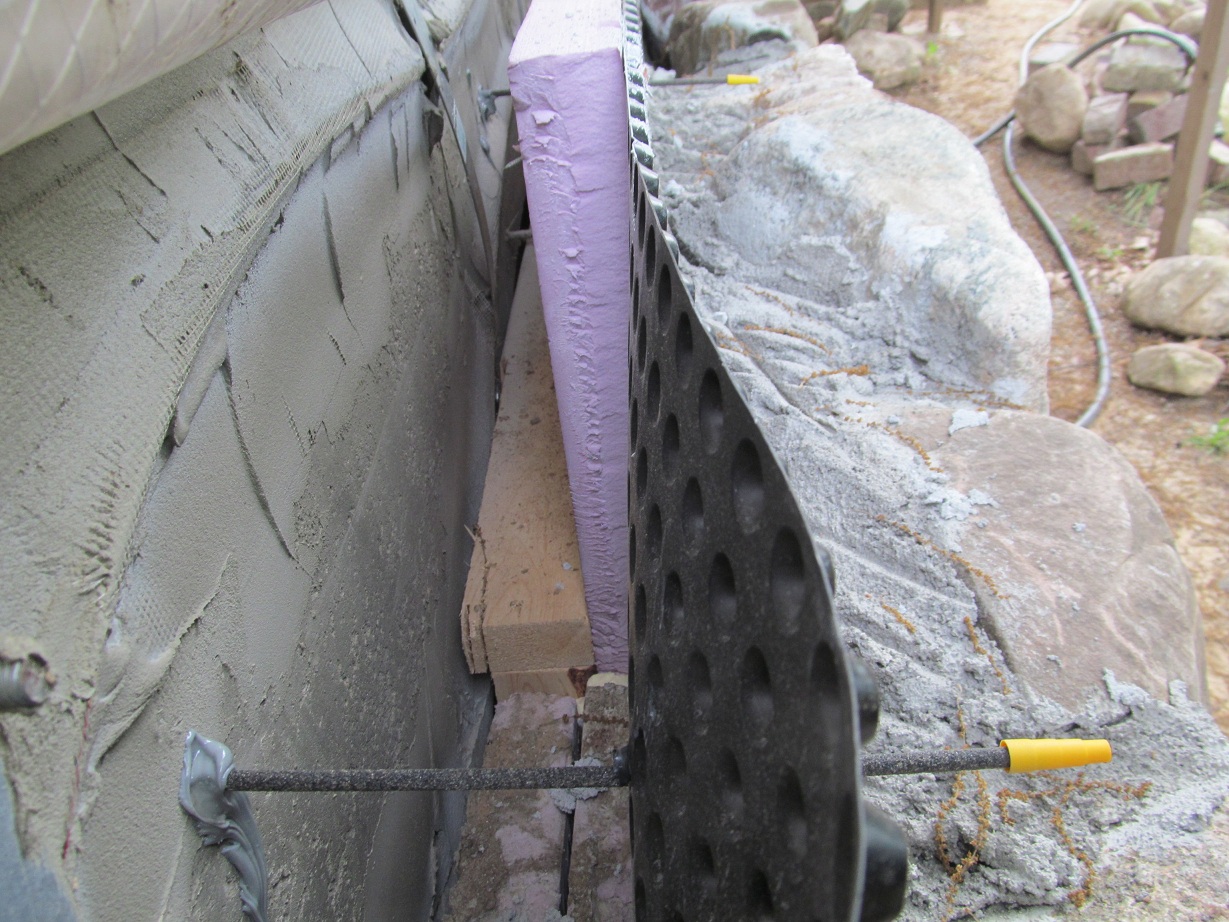

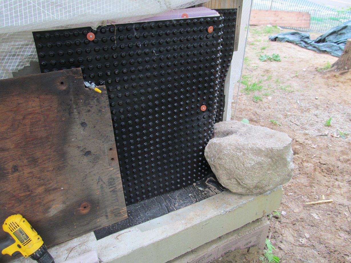
Above pictures show teplo ties connecting concrete arches to field stone stem wall. Also a small section of stem wall at the front porch is 8″ thick poured concrete with 2-3″ of veneer stone and showing wall ties in this area.
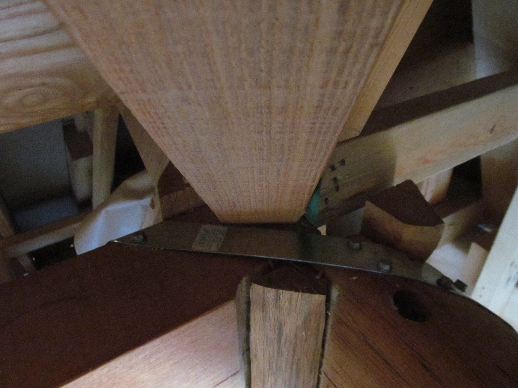
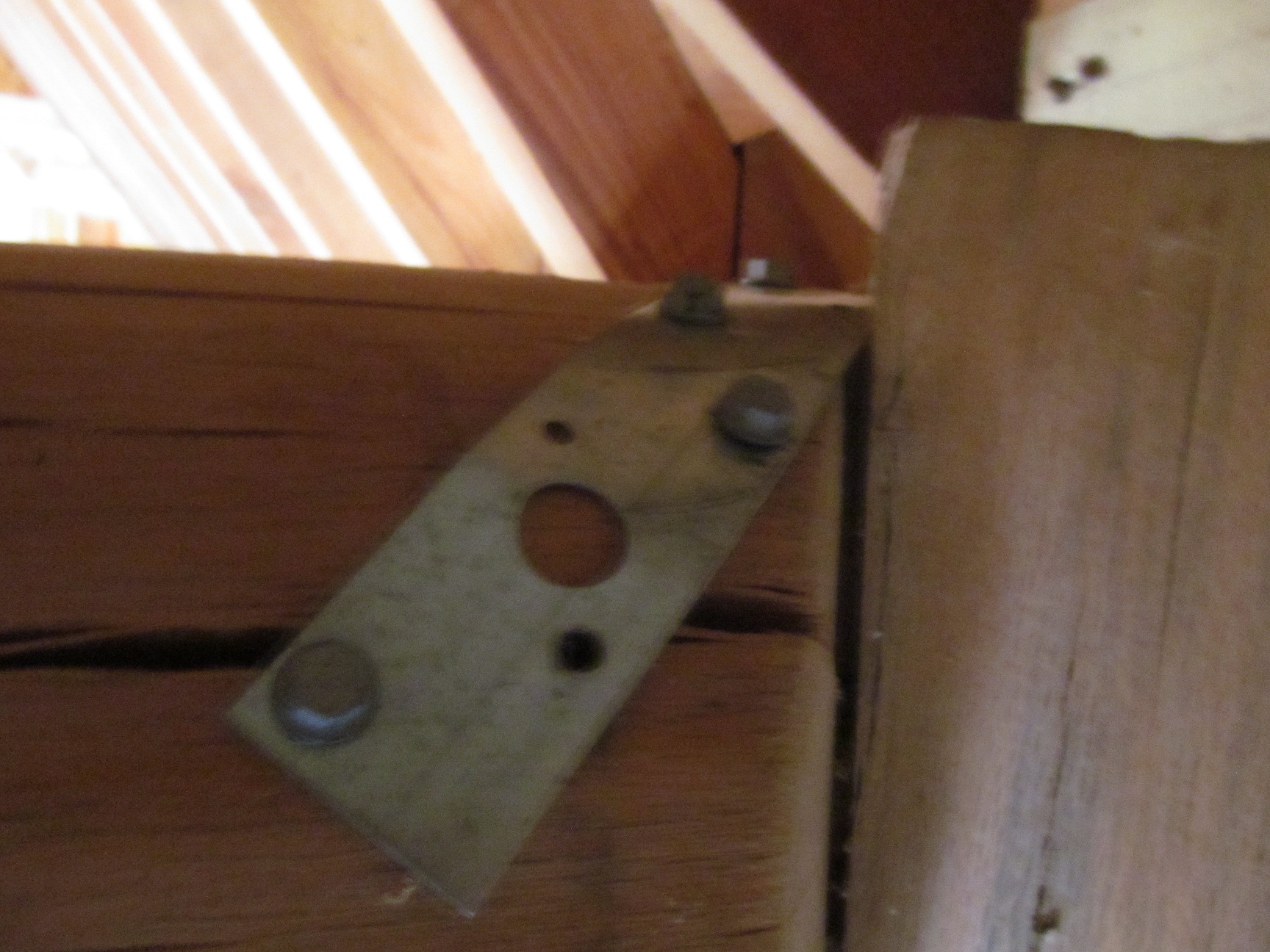
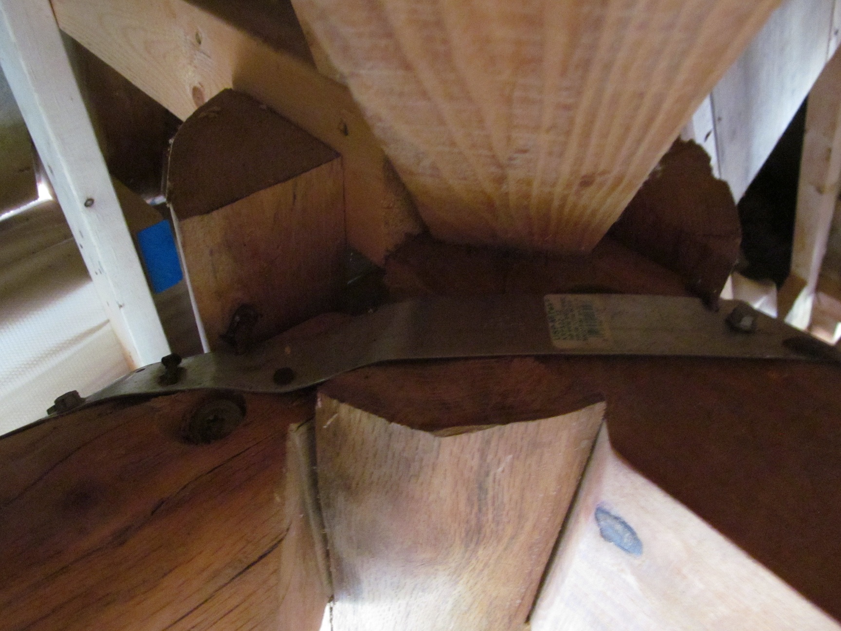
At top of posts at the hip roof, the corners are tied with a steel strap:


Floor of sleeping space in loft is 3×5″ roughsawn ash with spacing of 14.5″-15″ o.c. with span of 11′-1″. Edge beam pictured is 5×8″ ash.
Ash rafters are 3×5″ 15″ o.c. ash fastened with 1/4″ SPAX bolts: tensile strength 1169#, shear 766#, (southern pine) withdrawal 279#/inch and head pull-through 69#.
Upper rafters attach to 2×12″ ridge and are 2×8″ 15″ o.c. They are yellow pine one continuous piece over 18′ long.
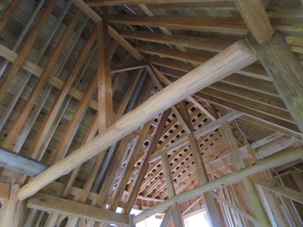
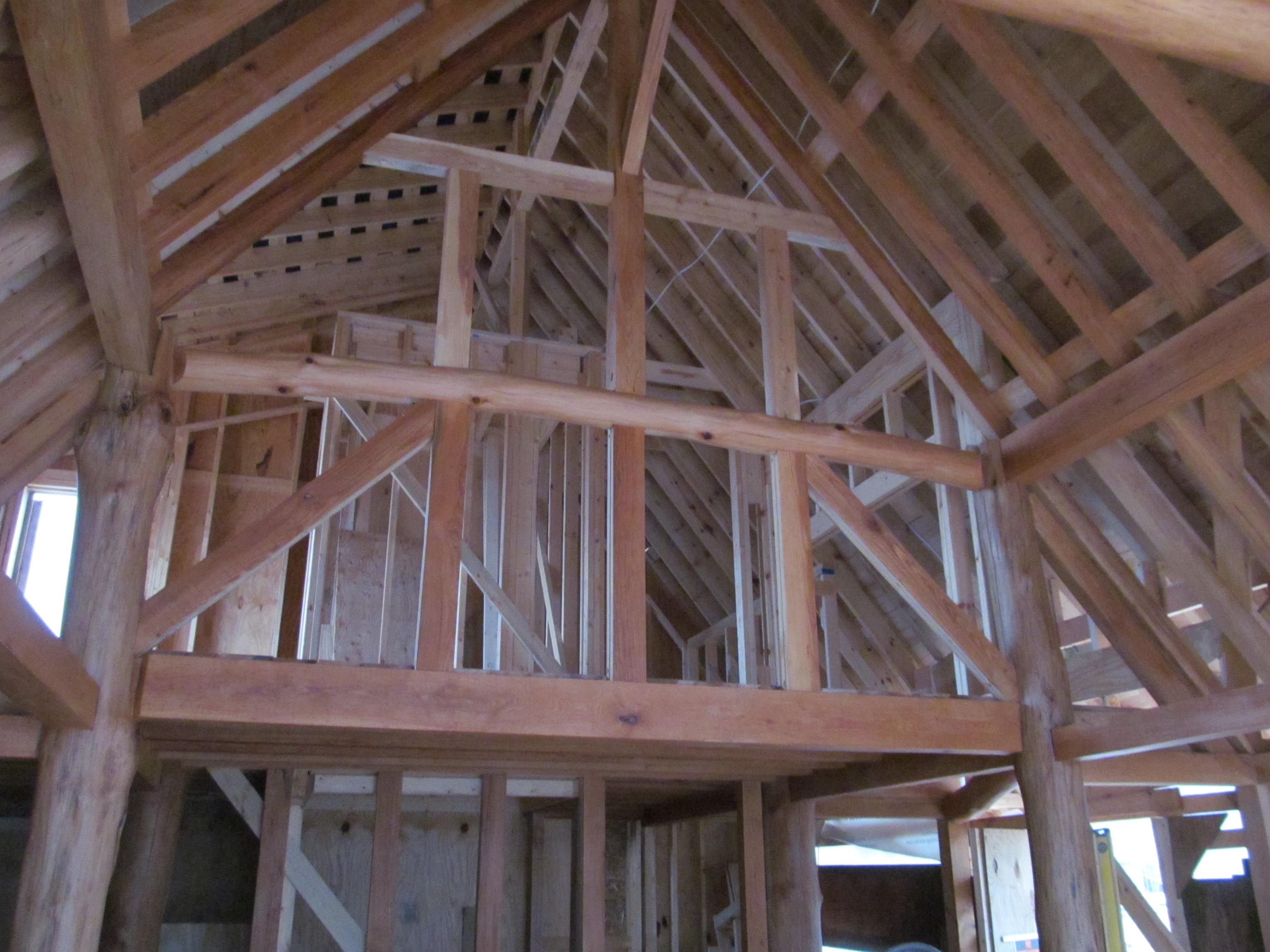
Frame under construction:

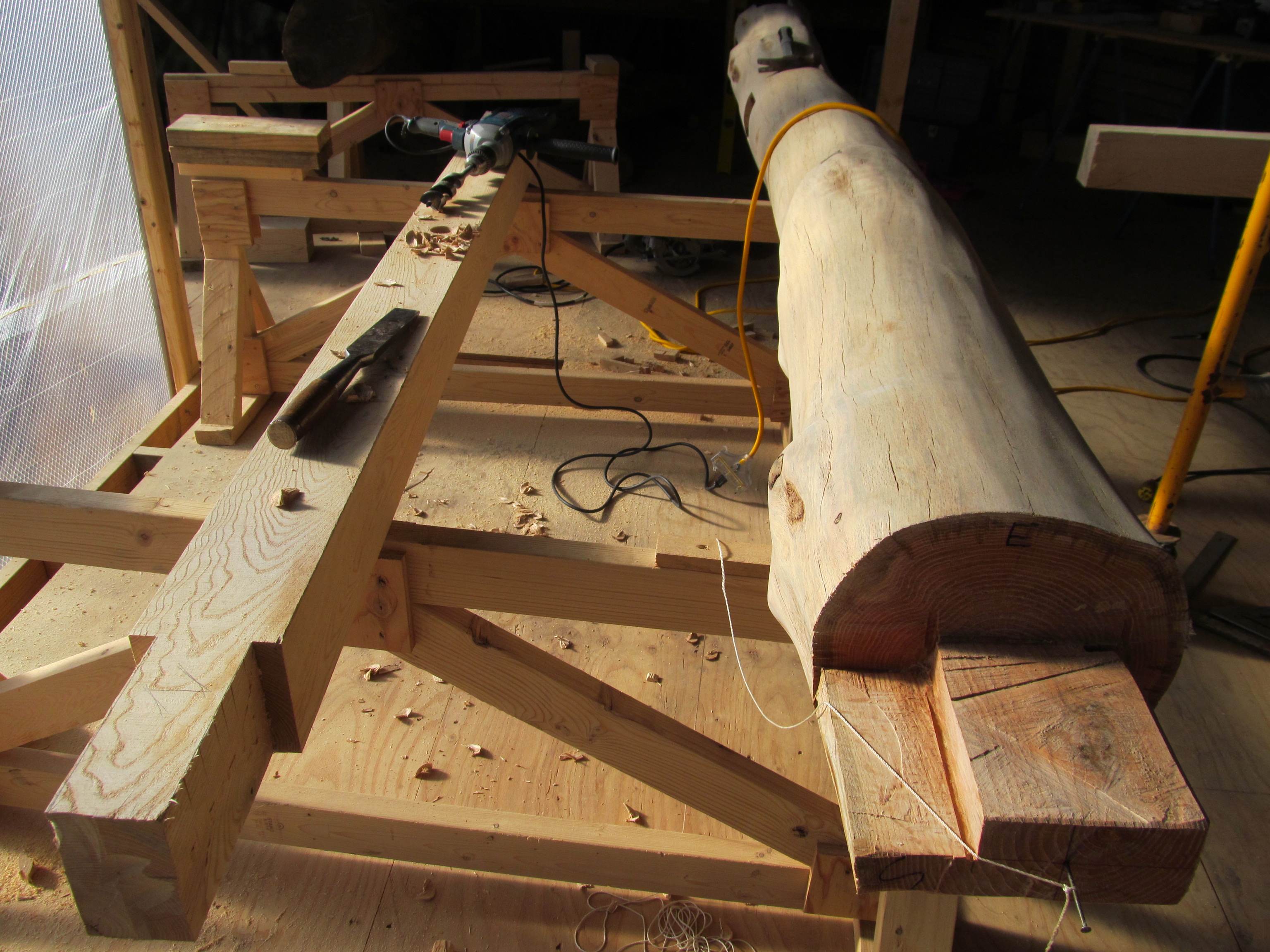
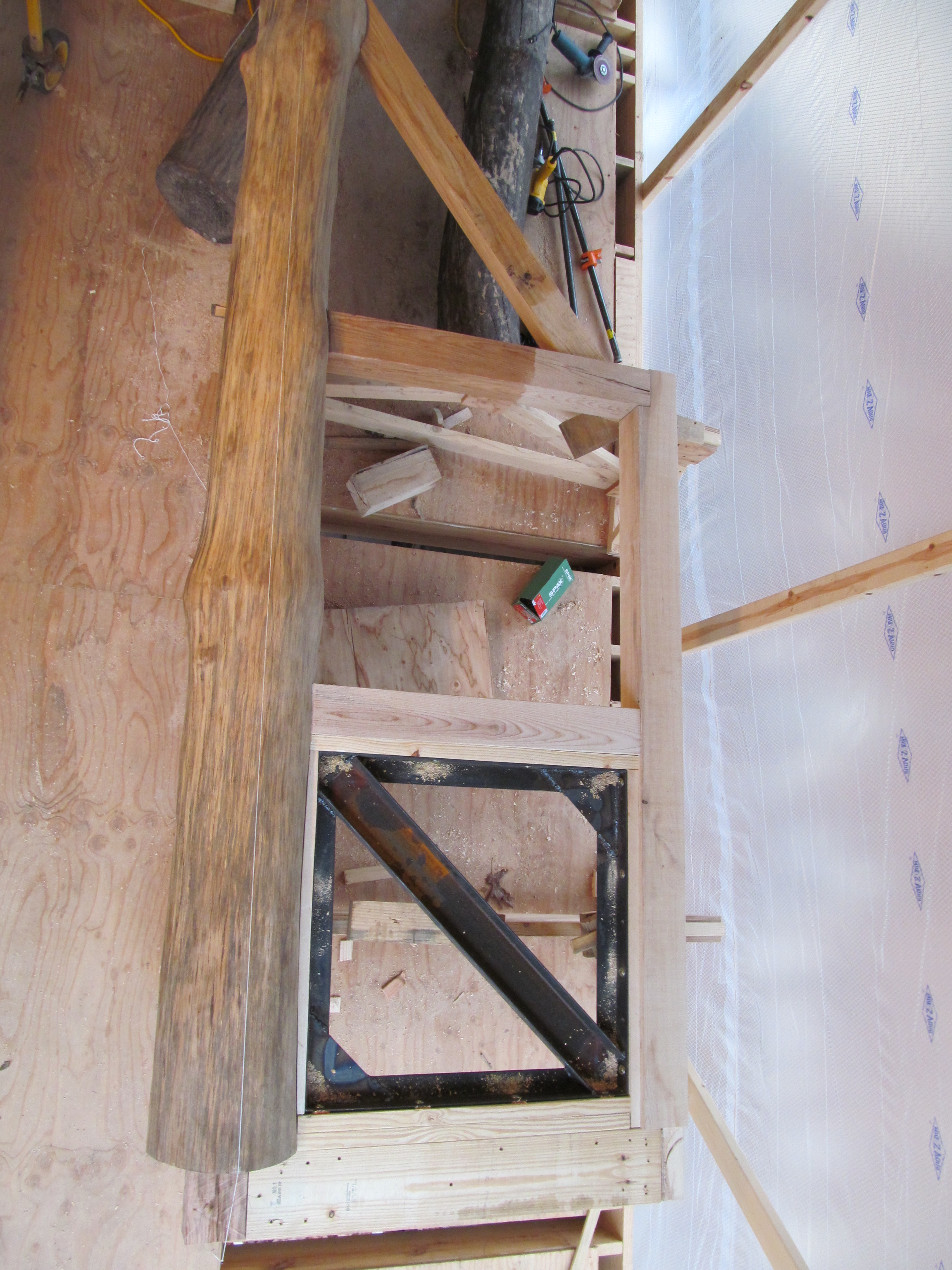
The house is a three aisled hall house. The tree trunks act as columns to order the space into bays and will weigh around 300# (10″ diameter, 12′ long oak at 45#’s/cu ft = 300#’s) I built big trusses from the tree trunks and 3×5 and 5×5 ash and welded up a steel brace from angle iron and channel.
This is bolted on all 4 sides to the wood with four 3/8″ Spax screws (tensile strength 2402#, shear 1435#, southern pine withdrawal 361#/inch, southern pine head pull-through 787#.) Corner bolts are 1.5-2.5″ from corners and the rest spaced evenly.
The steel truss sections are 33×33″ and are made of 3/16″ steel. Angles are 2.5×2.5″, fillets are triangles hypotenuse=12″, brace is 1.75×5″ channel. Welded both sides.


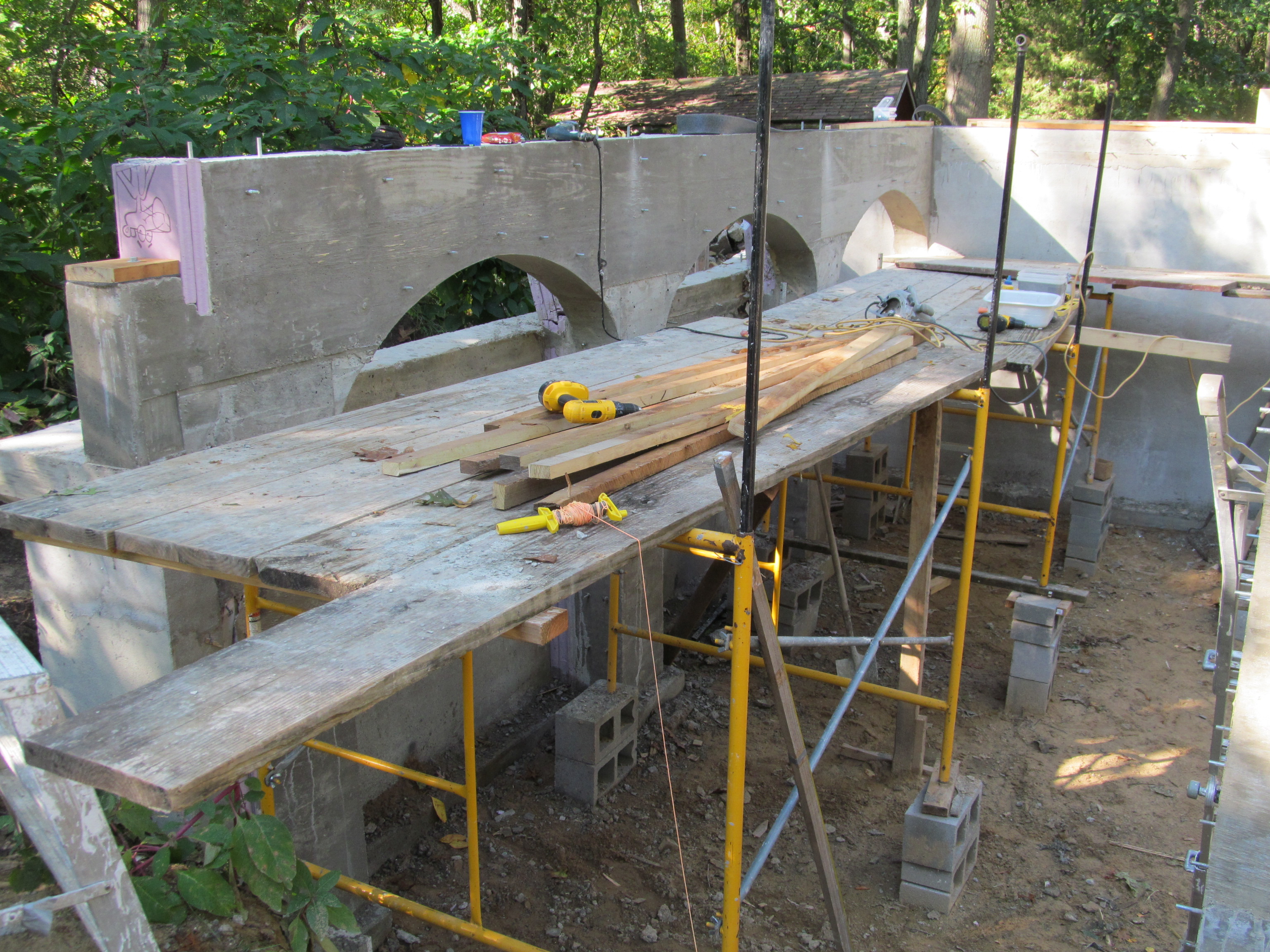
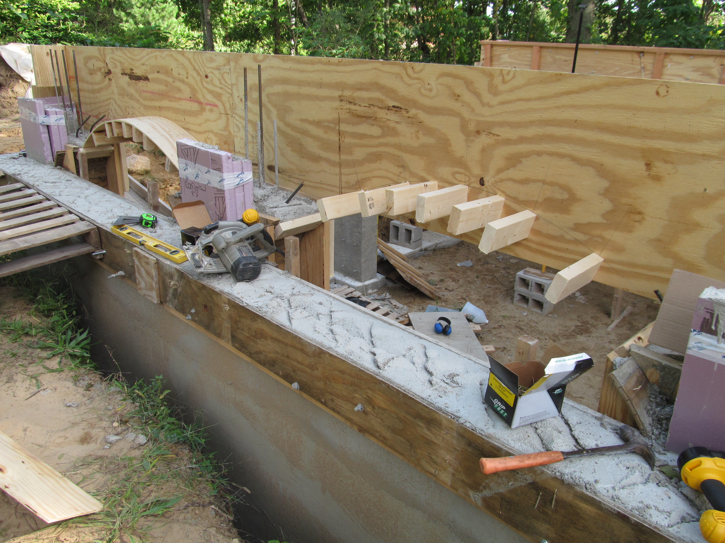
The frame rests on concrete posts:

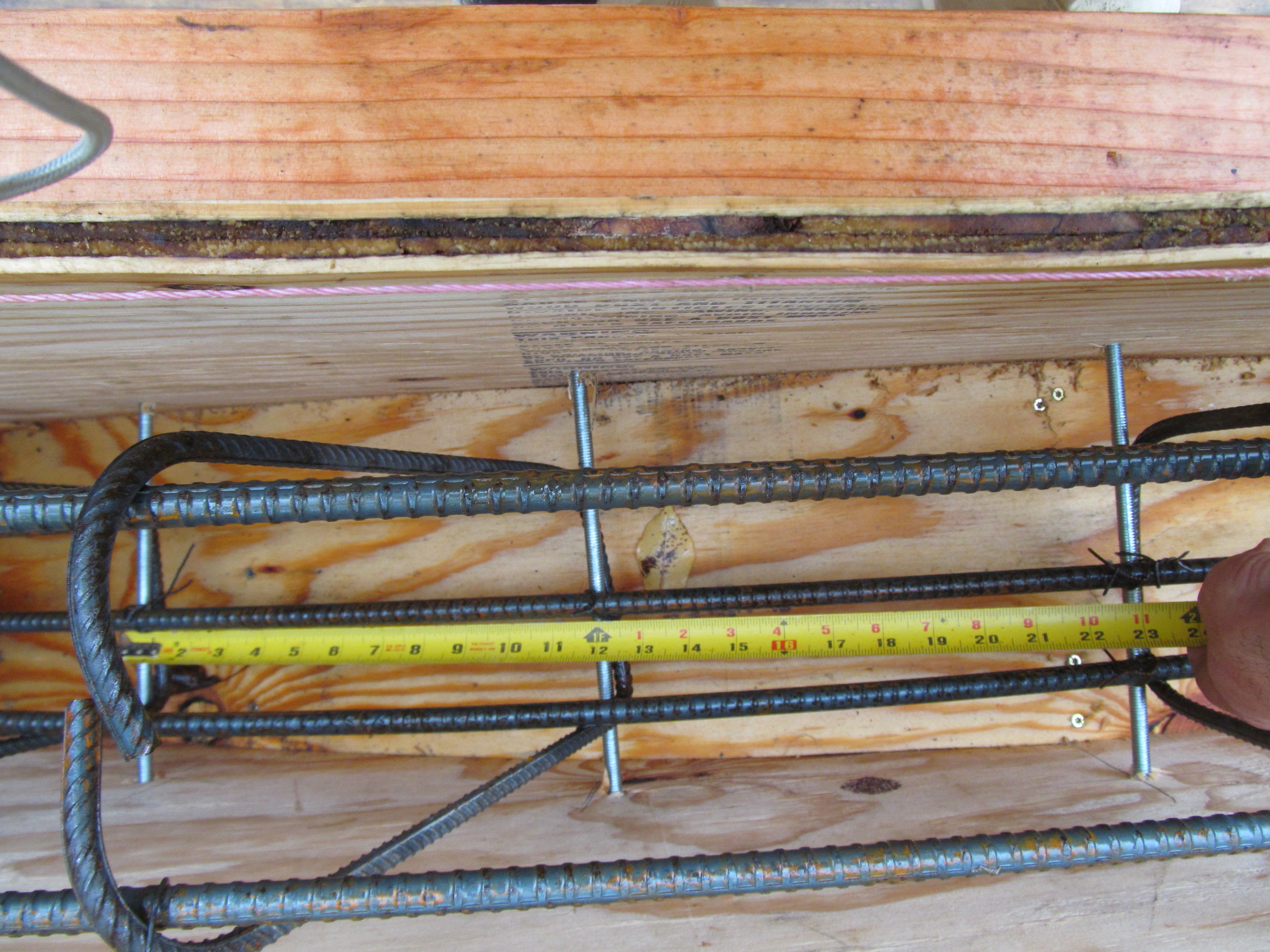
Arched beams are 9.25″ in width. Start at 36″ in depth and at thinnest point (top of arch are 15.5″) with 3 #4 rebar at bottom (3″ up) for an effective depth of 12″. Top of beam have 2 #4 rebar 3″ from top of beam. The posts support the post and beam frame, the beams only support floor joists for the living areas (40# live weight and 20# dead weight) and cob wall 8′ tall at +-100#’s/cu ft. The beams do not carry any roof loads. I made stirrups from #3 rebar; 5 equidistant along the span of each arch. Control joints are made with sheet metal placed to weaken an area of beam (along with cutting relief cut with concrete saw in line with sheet metal) over each column. From the top the sheet metal makes a “V” shape to make a key. See diagram below.

Outer wall is 8″ CMU dry laid with Quikcrete Quikwall surface bonding cement (first row on footer in mortar bed). 1/2″x12″ J-hook at corners of footer (3 cores reinforced per corner) and every 4′ with same cores filled and #4 rebar in. Capped with 8″ bond beam with 1 #4 rebar.

Here are my stirrups and metal plates to make control joints.
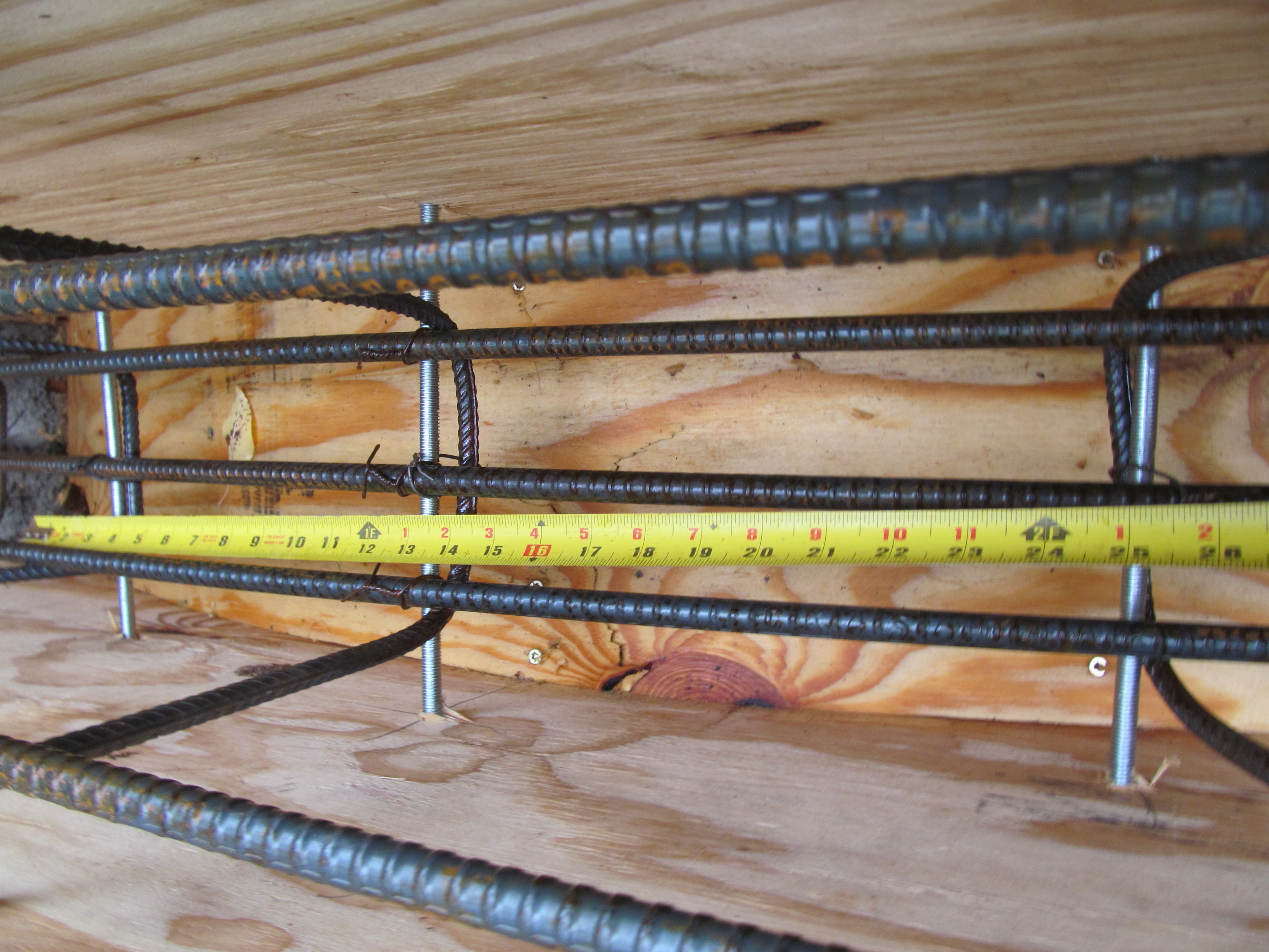

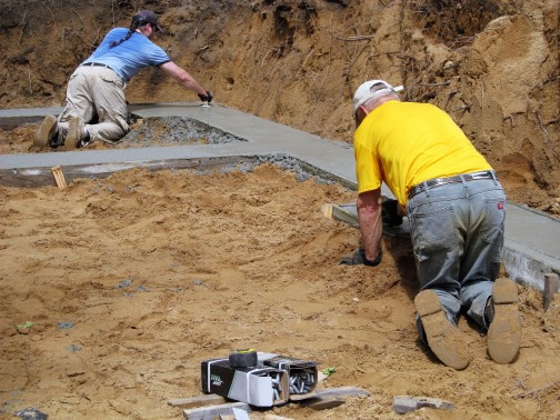
Here are the beams with all rebar and stirrups placed:


Columns are anchored to outer wall bond beam with 6 mm x 13″ Teplo ties (masonry ties made from extruded basalt embedded with sand with 1/20th the thermal conductivity of steel to eliminate thermal bridging) 4 at corners and 2 from each column to wall. Also columns are poured with 2 or 3 sided forms so the weight of the wet concrete during pour is squeezing against the 4-6″ of extruded polystyrene (“250” high compression board) so essentially wall and column are braced against each other.
https://www.twistfix.ie/teplo-tie-basalt-cavity-wall-tes


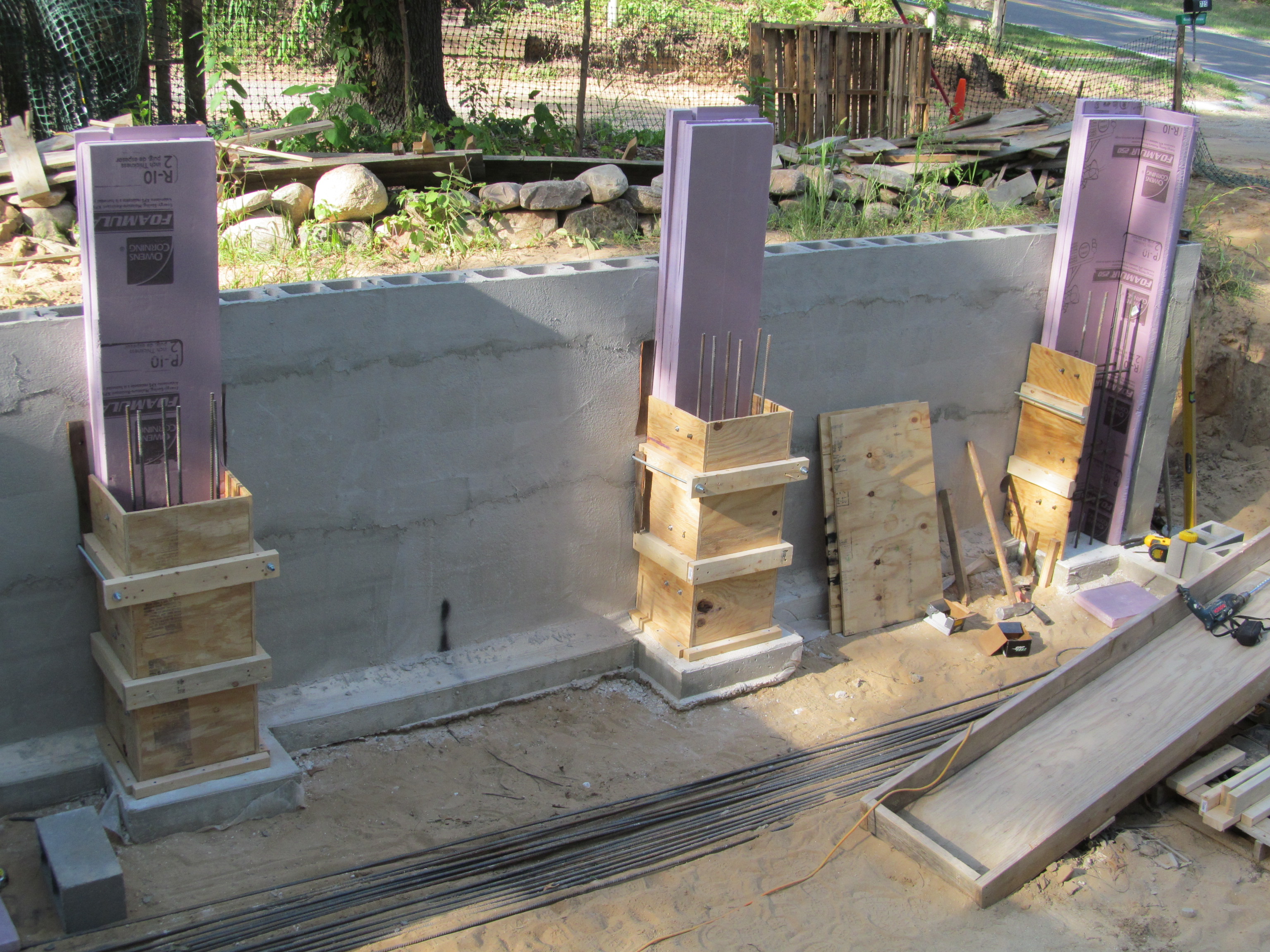
Concrete columns 9.25″x16″ anchored to footer with 2 12″ J-hooks. 6 #4 rebar placed in column. 12″ overlap of rebar between bottom and top half of column. Clear span of beam is 75″ or less.
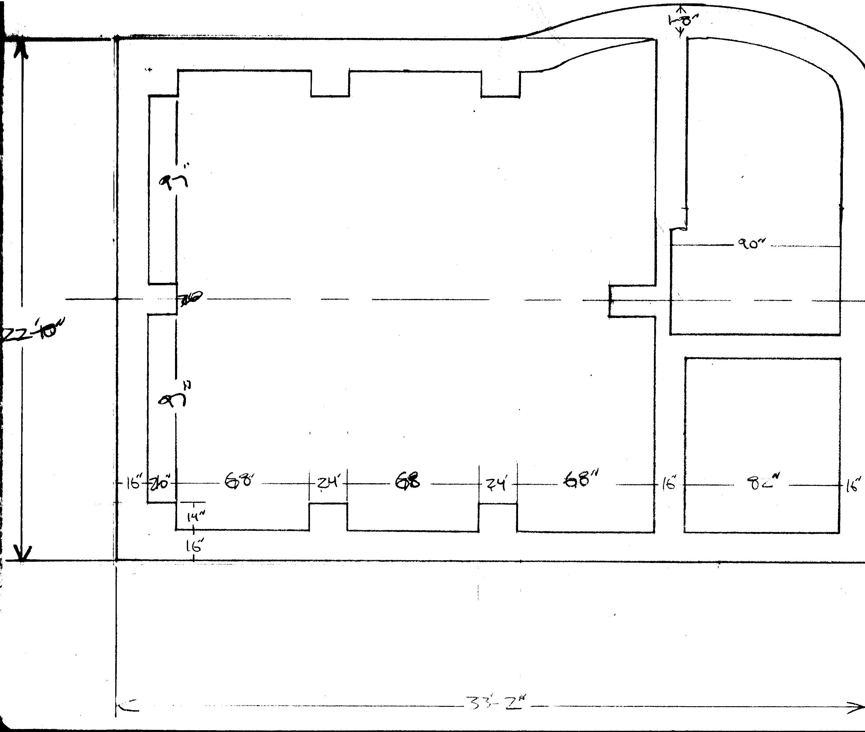
Footer plan: 8″ deep of 4000 psi gravel mix concrete (all concrete used in house is 4000 psi) with 2 #4 rebar placed 1/3 of the way up from bottom. Subsoil is 100% fine sand.


