12-16-20
Here’s another idea which is all steel and connects directly to the existing steel truss. The 3×3″ angle with welded cap would fit up under the end of the tree trunk and the metal strap (maybe a 3/16″ plate 4″ wide?) would go up to the steel truss:

It could bolt on to the base angle and the channel and would be at about a 25-27 degree angle and the strap would be about 40-42″ long or could also attach to the vertical angle as well if it were at least 48″. There is an approx 1/2″ gap on each side which I could slide the angled plate up through.
Even stronger would be a 3×3″ channel with plate steel coming up on both sides if the one sided hanger is too unbalanced. The channel piece would need to face downward as the bottom of the tree trunk is a full 3″.

The angled plate coming up on other side of the truss could be connected with an angle iron like this:

12-15-20
Ben,

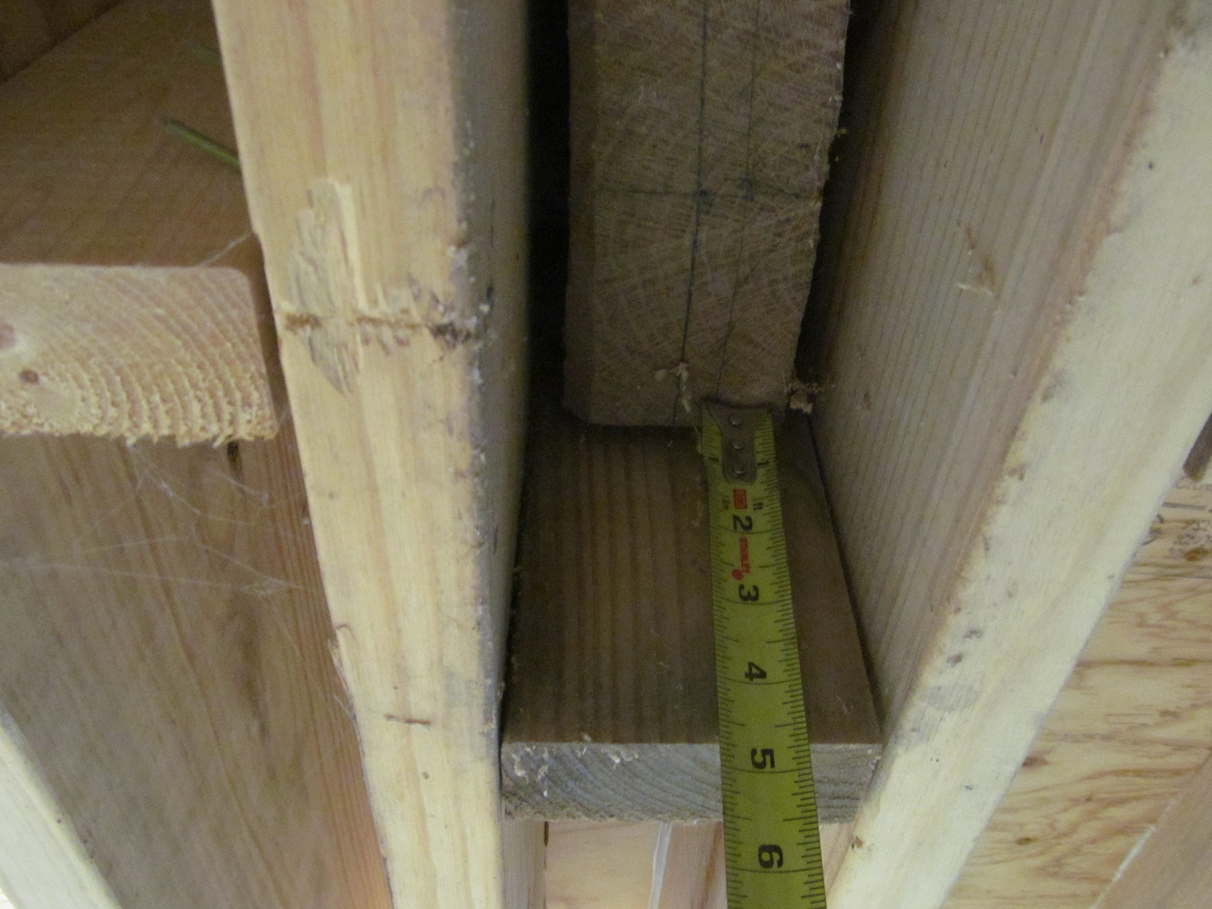
The bottom of the tree trunks and the rest of the truss mortice down into the 2×12 framing by 6 1/2″.
Could I bolt a 3″ x 3/16″ steel plate (or even a 3×3″ angle) on the bottom and put multiple screws up into the end of the tree trunk and the double 2x material?

The plate could also be through bolted from the steel truss section through the 2 drilled holes which do not have screws in them. The holes are 1/2″ diameter, but could be bored out to a larger size or more holes could be added.

The plate or angle could have an end cap welded on to it if needed.

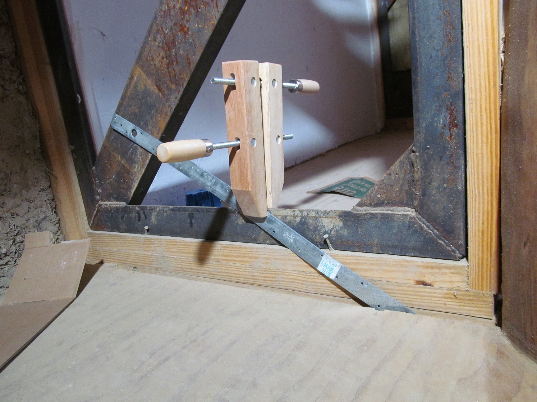
Something like what is pictured below, but much stronger and not in the usual orientation:

______________________________________________________________________________________________
April 29, 2020
Hi Ben and Tom,
I’m adding this new set of photos to add some clarity to the drawings I am sending you. Hopefully the photos along with written descriptions will help illustrate the structure of the house.
One of my cross section drawings shows the loft end. This picture is taken from the living room towards the bedroom loft upstairs.
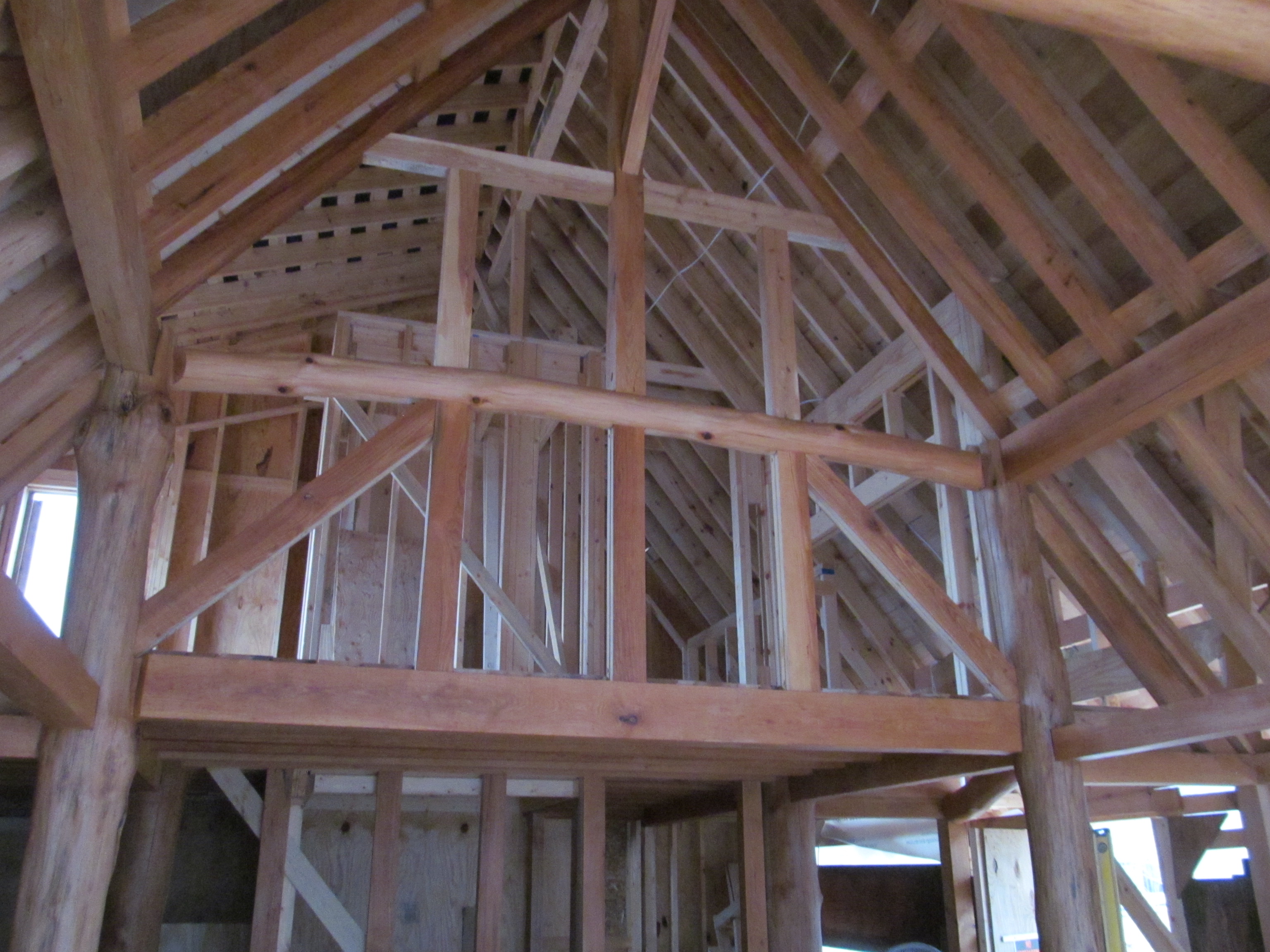
Here is the floor of the loft, which is also the ceiling of the kitchen and living room area under the loft. 5×8″ beam, 3×5 floor joists.

This picture shows the view towards the hip end before the oak wall and window has been installed. The size of the bays is 7′-6″ o.c.

That is a lot of weight from the hip roof bearing on the round beam pictured above. The 5×5″ white oak gable end can take some of this load:
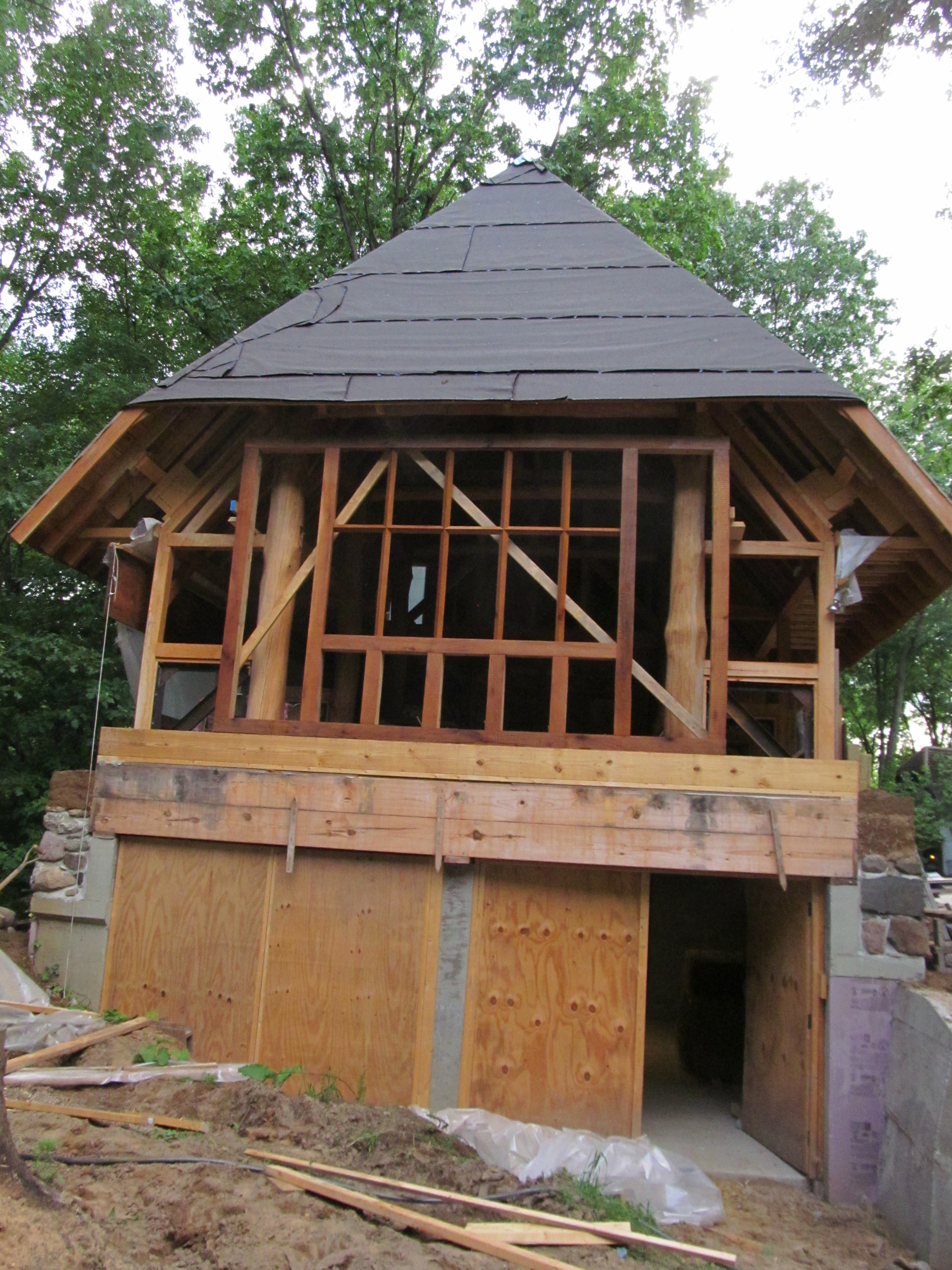
The oak wall sits on 2×10’s with 2″ spacers:
This wall bears on the concrete side walls, but unfortunately the concrete pier in the center is set back a few inches so that it can be insulated and not make a massive thermal bridge to the inside of the garage. These stacked 2×10, and two 2×12’s are now connected by plywood and some blocking which can be inspected at a site visit. There is a “knee wall” framed of 2×4’s from the top of this oak wall up to connect it to the roof structure. Also, the gable end wall is a double wall, to allow space for insulation, so there is an internal wall which is framed of 2×4’s which can also take a percentage of the weight of the hip roof.
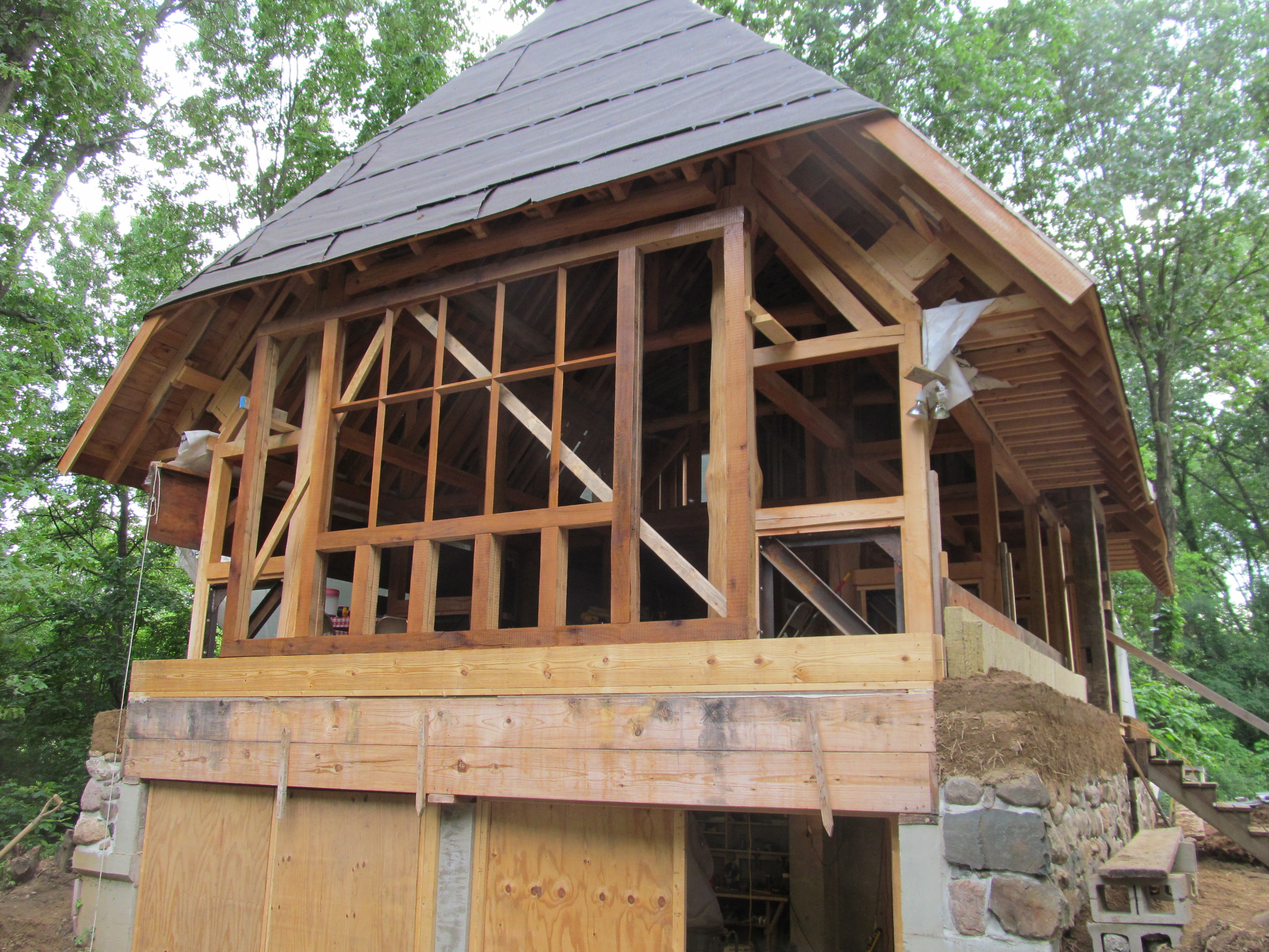
I wanted to superinsulate the roof to R70+. Pictured below, the ash rafter structure is in place, and the 2×12 top ridge can be seen, the top of which is about 37″ above the top of the 5×8″ ash ridge. The part of the roof to the west (right side of picture) is the bedroom which does not have any exposed ash rafters, it will have a drywall ceiling.

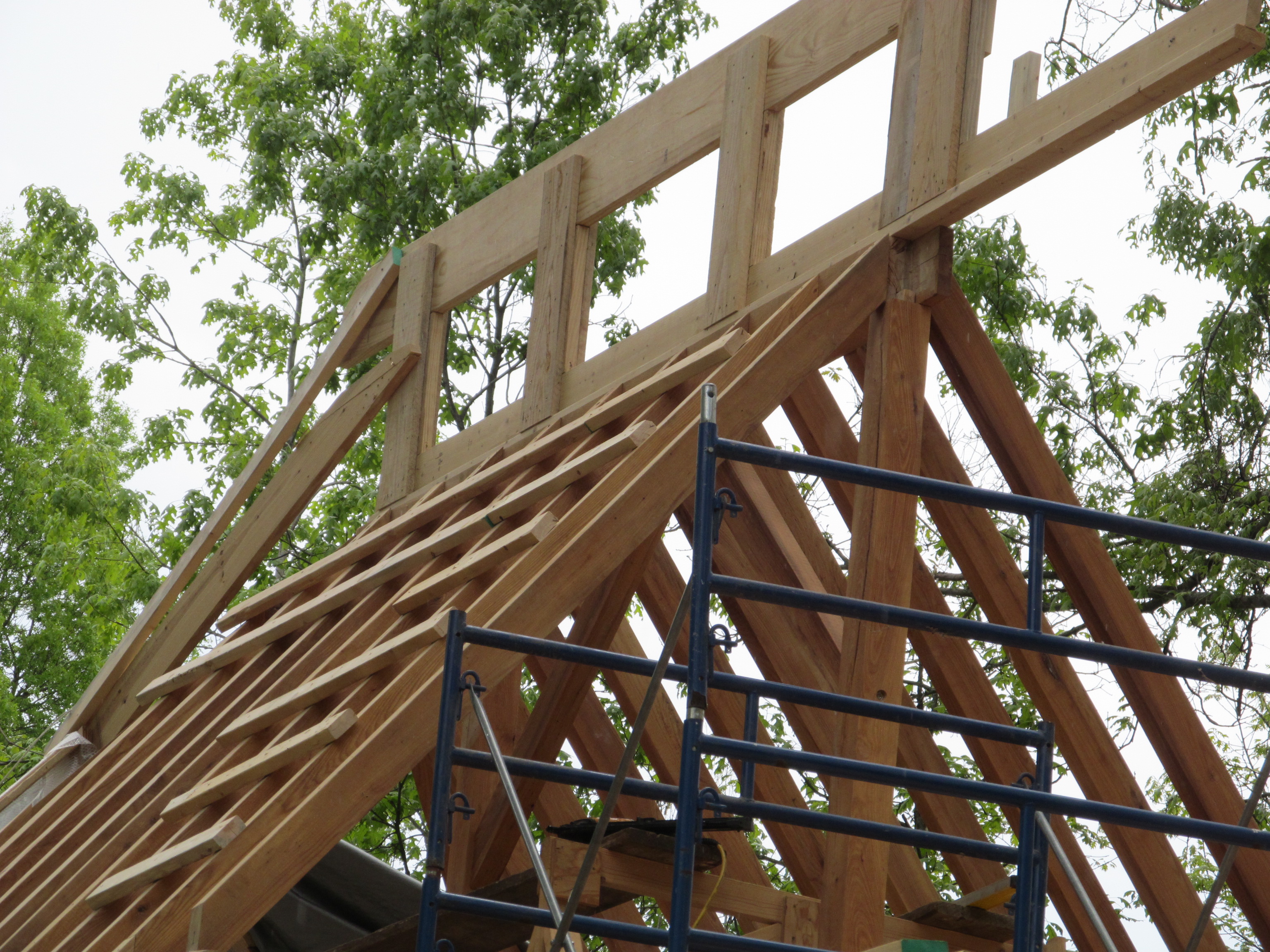
There is some “blocking” shown in the drawings. Can be seen in the left picture below. This supports the lower end of the 2×8″ top rafters which then have 3×5″ ash rafter tails sistered on. (the horizontal 2×4 shown is a temporary brace) The 2×8 rafters are nailed to the ridge and their bottom ends bear on the blocking which is above the wall which rests on the footer. As far as vertical loads, the 2×8’s don’t need the help of the ash and round log timber below. The span of the basement is 18′-4″ so span from ridge to edge is only 9′-2″, well under the max even considering the extra 10#’s of dead weight of the slate.
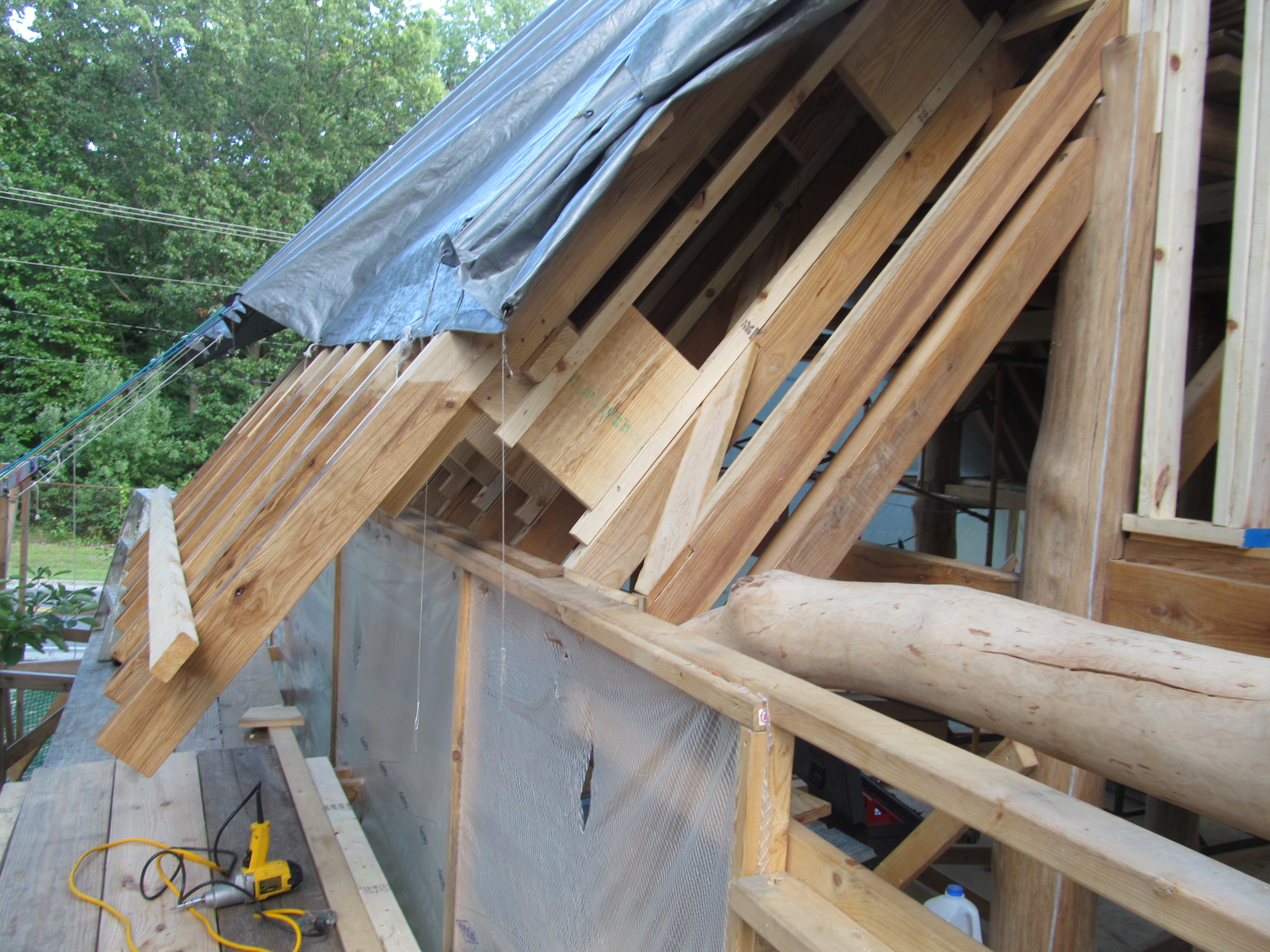

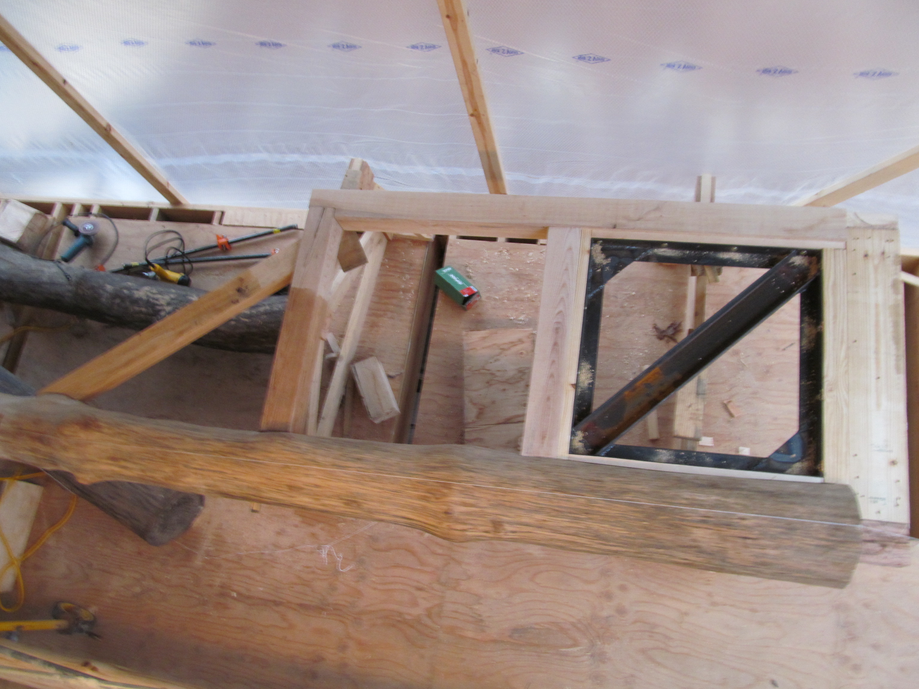
Here is a photo of the hip framing. Note the zig-zag framing which blocks up the top hip…all this space is for blown in cellulose.

I built 6 “trusses” on saw horses, then had a few friends come over to tip them up a pair at at time. I left 4″ x 3’+ feet mortises in the subfloor for them to sit into. Where the full round of the tree truck stops is where it aligns with the sub floor. The +-7.5″ below that tenons into the floor.
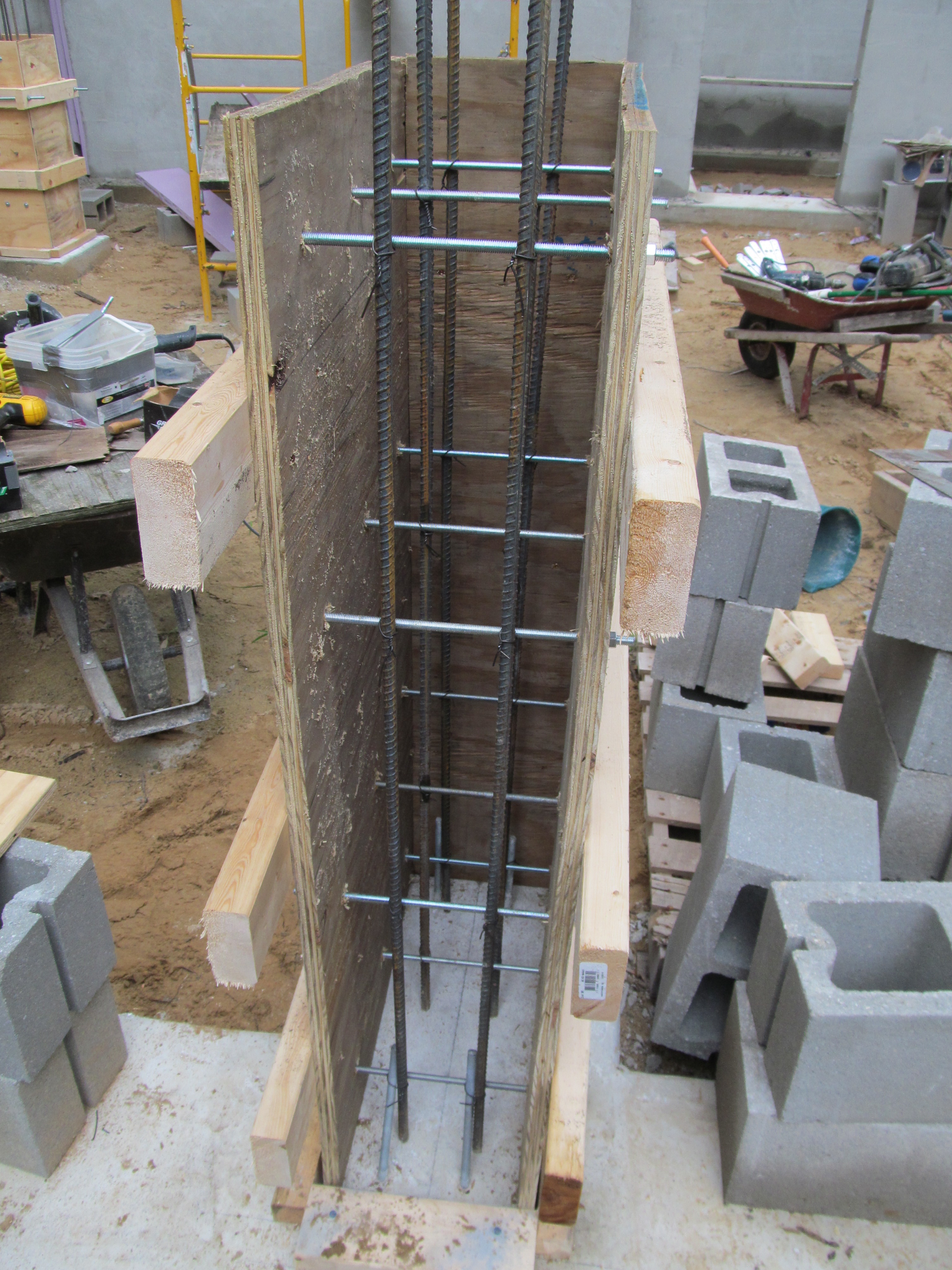
Here is a view of both sides of the steel reinforcement. There are four 3/8″ SPAX bolts on each side. I predrilled 7 holes per side, so can easily add more bolts if needed.


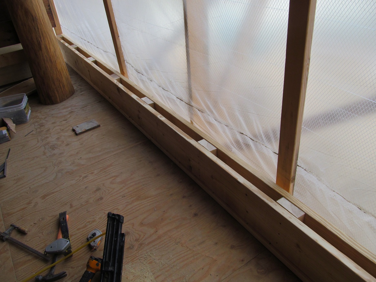
Here is a view showing the cavity wall prior to starting the cob. The 5×5 ash post bears down to the concrete pier. In the middle is 6″ of extruded polystyrene. The inner leaf of the cob wall starts right in the openings in the subfloor edge. Two layers of 3.5″ R15 mineral wool batts take over for the XPS as the wall rises, and cob gets built onto the field stone.

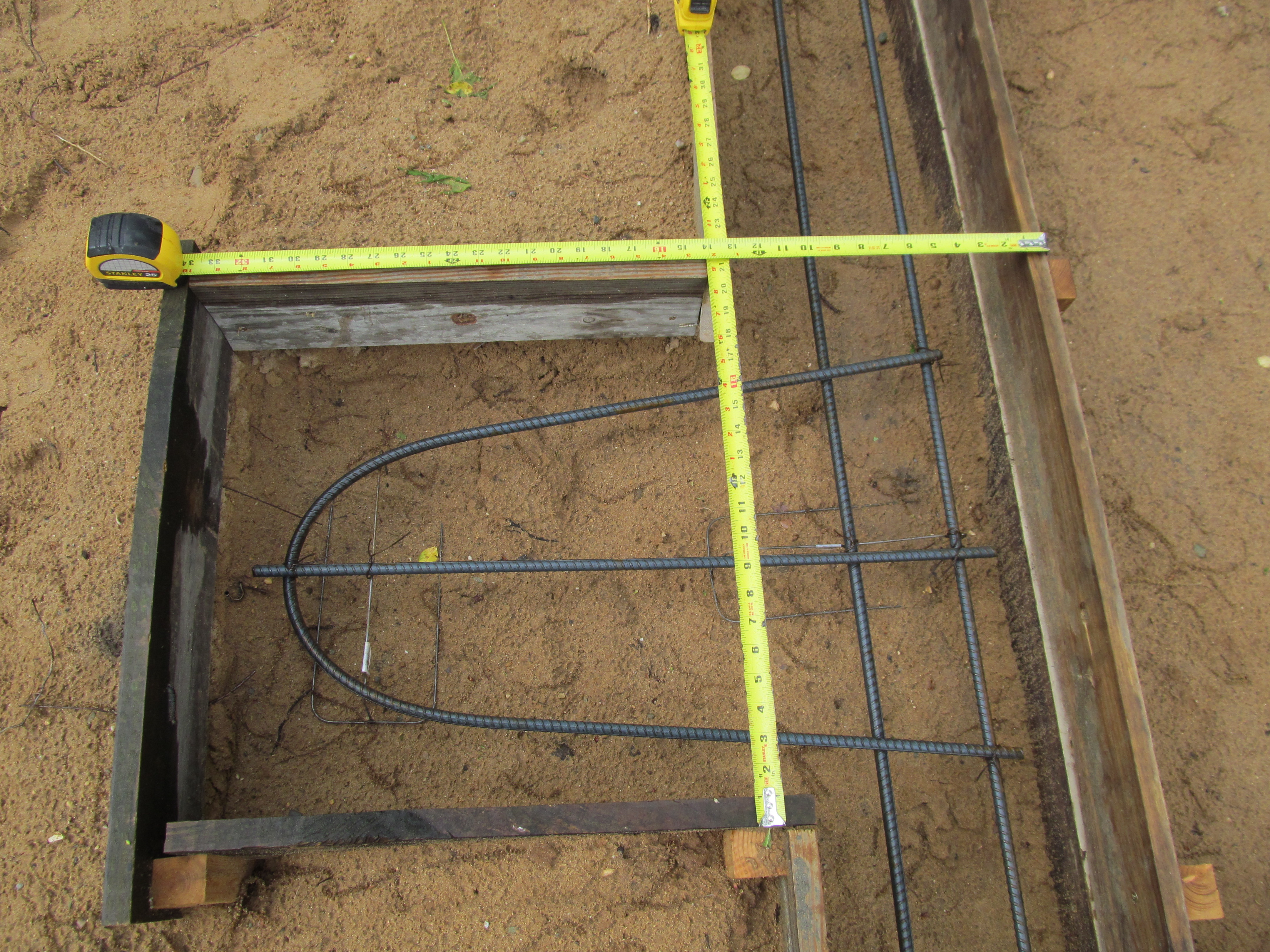
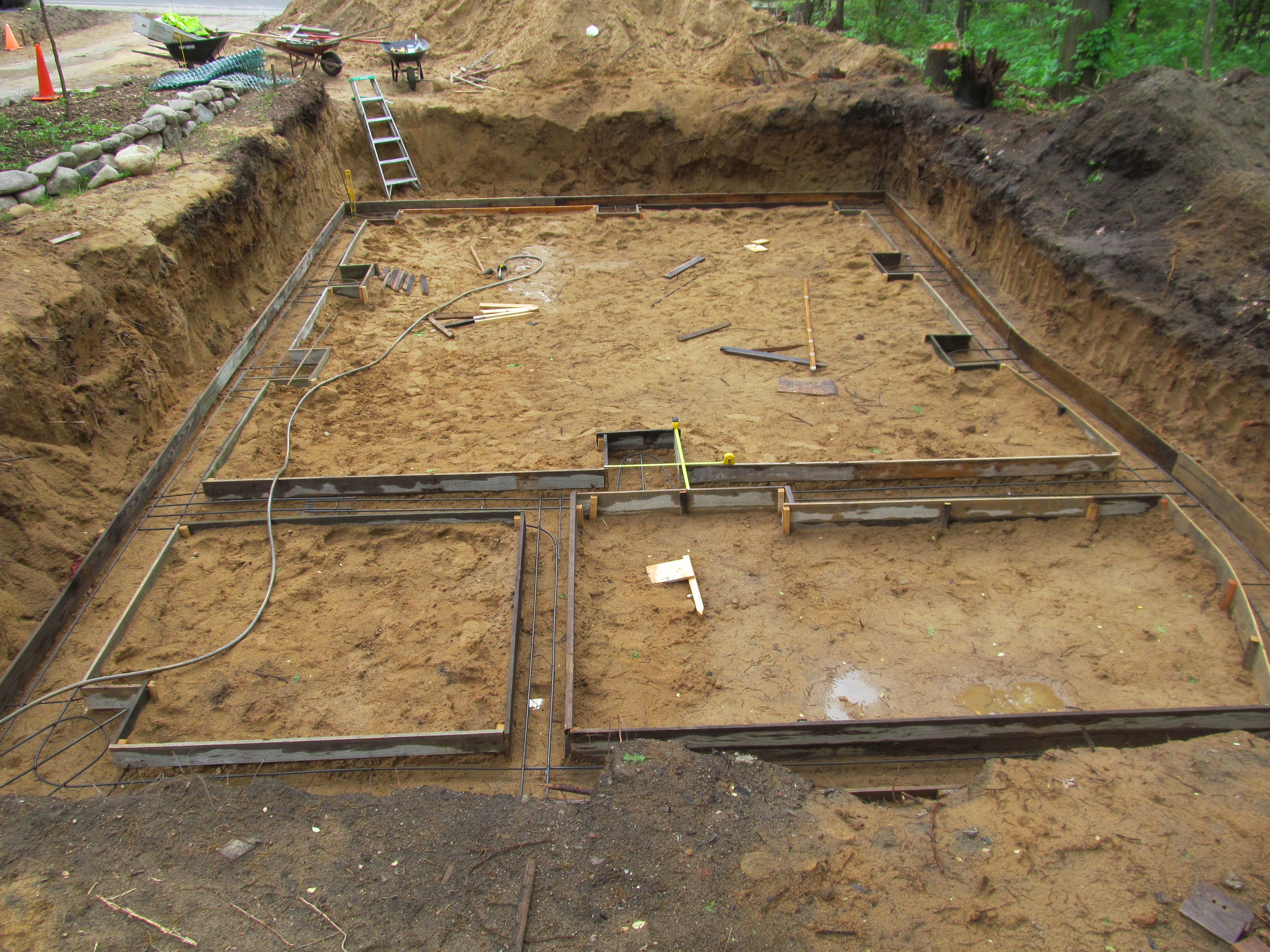
Here are some more footer pictures:
The pier in the middle of the garage doors:

Here is an internal concrete wall in the basement which is almost all poured solid:

This is a small footer poured later after the original footer was poured. It supports the wall which in the future would be the elevator shaft wall. There are 3 stacked closets which are the size of an elevator so in the event someone wanted to install an elevator this shaft could be easily opened. With the west end footer, this small footer, and the footer under the concrete wall pictured above, this makes 3 footers in less than 10′ which have vertical walls from footer to roof ridge! So the west end of the house should be good as far as vertical loads are concerned.

A few more footer shots: